Oct 012014
 

NOTE: this is the latest official “PDF Review.” (Two were supposed to be released in September, but events prevented that. So this is the first of four to be released on October.) The idea is to present interesting online resources for those interested in  the sort of aerospace oddities that you can find in the pages of Aerospace Projects Review. This little project is supported through my Patreon campaign; at current levels, I’ll post two such reviews per month. If you’d like to see more, or just want to contribute to help me along, please consider becoming a patron.

The Boeing 2707 supersonic transport was cancelled in 1971. The cost of developing the aircraft, coupled with the increased fuel costs due to the oil embargoes of the early 70’s, doomed the effort. However, NASA continued to spend money on studies of supersonic transports throughout the 1970s and into the 1980’s, focusing their interest on SSTs with advanced aerodynamics and propulsion systems in order to reduce fuel burn and thus operating costs.

Pages from Advanced supersonic technology concept study reference characteristics-3

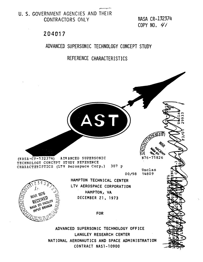
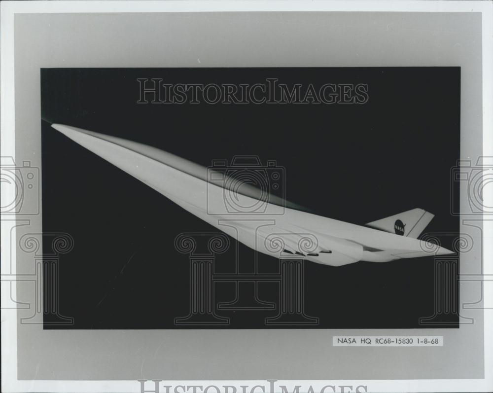
One such study was performed by Ling Temco Vought for NASA-Langley in 1973. The study  described a four-engine SST design to serve as a baseline for further study and refinement. Basic characteristics of the design:

  • Mission range of 4000 nautical miles with 292 passengers
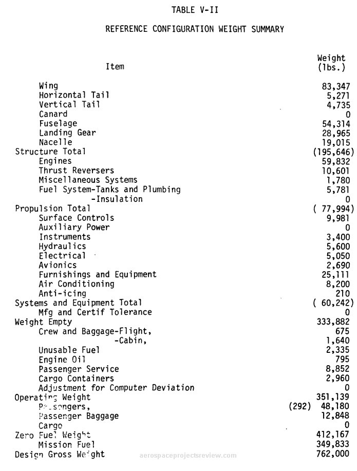
  • Take Off gross weight of 762,000 pounds.
  • The engines were non-afterburning, yet provided a cruise speed of Mach 2.7 at 60,000 feet.
  • For a standard-day sea-level takeoff, a maximum 10,500 foot runway was needed.

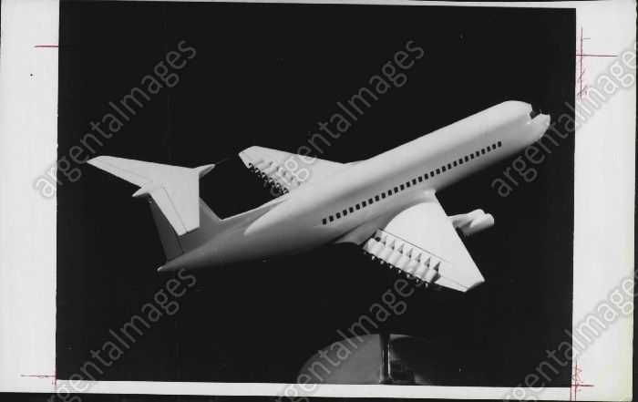
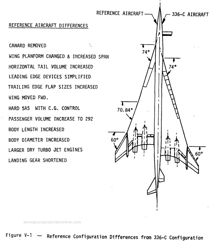
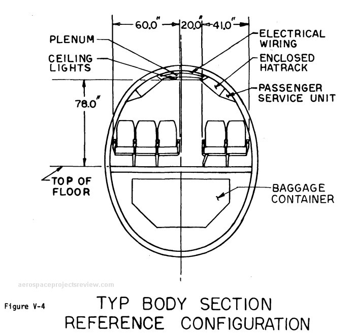
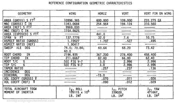
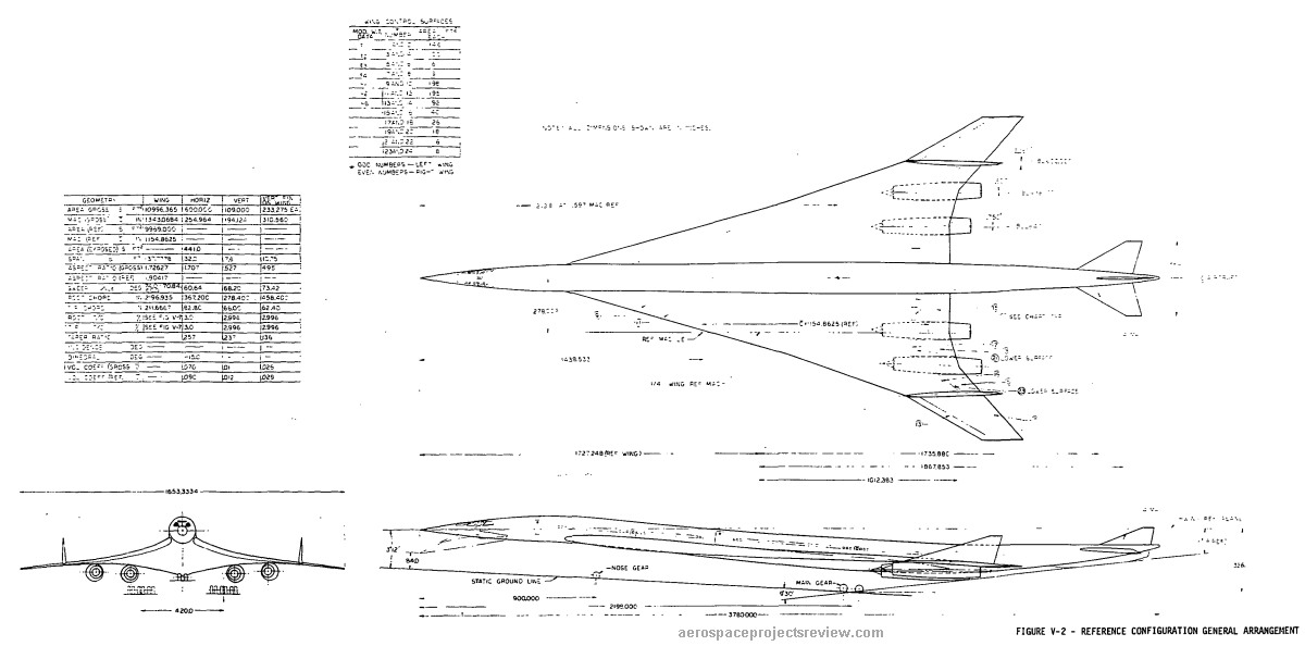
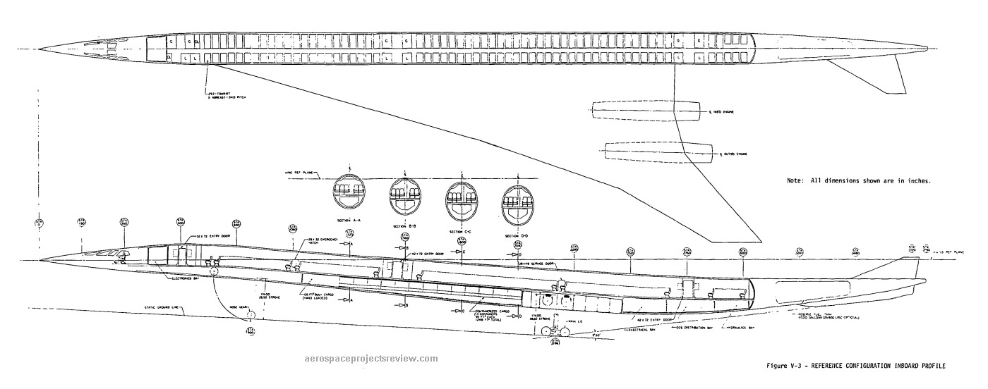
The initial design was based on a previous Boeing design from 1968, the Model 733-336C. While broadly similar to the earlier design, the LTV design deleted the Boeing’s deployable canard, used larger non-afterburning engines, moved the main wing forward, increased the size of the tail and cranked the wing sweep slightly. Additionally, the four-abreast seating of the Boeing was changed to five-abreast in the LTV design, with an increase from 234 to 292 passengers. This was made possible by a slight enlarging of the fuselage.

Pages from Advanced supersonic technology concept study reference characteristics_Page_01

Pages from Advanced supersonic technology concept study reference characteristics-2

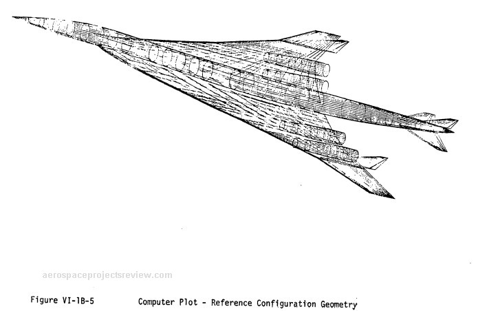
The very latest in computer graphics, 1973 style.

Pages from Advanced supersonic technology concept study reference characteristics_Page_14

Pages from Advanced supersonic technology concept study reference characteristics_Page_13

Pages from Advanced supersonic technology concept study reference characteristics_Page_10

Pages from Advanced supersonic technology concept study reference characteristics_Page_05

Pages from Advanced supersonic technology concept study reference characteristics_Page_04

Note: the following two illustrations were stitched together from separate pages in the PDF. The full resolution versions are available to all APR Patreon patrons HERE.

Pages from Advanced supersonic technology concept study reference characteristics_stitch1

Pages from Advanced supersonic technology concept study reference characteristics_stitch2

The NTRS abstract page:

Advanced supersonic technology concept study reference characteristics

The direct link to the PDF file on the NTRS:

Advanced supersonic technology concept study reference characteristics

 Posted by at 7:00 pm
Sep 292014
 

Currently up on eBay is an original watercolor illustration of a McDonnell-Douglas cargo plane concept. Details are lean, but it looks like it dates from the 1980’s.

ebay 2014-09-29 b

A multibody design make sense for heavy cargo lifters. By spreading the load across the wing, rather than suspending it from a single point, the wing is stressed considerably less. Of course, drag is noticeably increased and runways need to be wider.

This particular design seems a little odd… especially with the leading edge of the wing. Unless the aft fuselage is taller than the forward fuselage, or the wing is tilted up at a substantial angle of incidence, then the leading edge of the wing should be submerged into the upper fuselage, as the trailing edge is. Artistic oversight?

 Posted by at 5:05 pm
Aug 252014
 

As the OPEC oil embargo of the 1970’s ground down the American economy and jacked up the cost of transportation, many studies were made of alternative propulsion systems. For cars and buses and the like, electrical systems were at least theoretically feasible, though even today fully electric ground transport remains problematic. But electric aircraft were out of the question. Similarly, jetliners could not be retrofitted to burn coal or wood, or run off solar power. So that limited the options. One available option was liquid hydrogen. Long since proven on rockets, liquid hydrogen had been used to power jet engines in an experimental capacity. In theory it makes great jet fuel… lots of energy, and produced with no need of oil whatsoever (a nuclear reactor and an electrolysis system can do it, though there are more efficient means). But there were two major down sides: it’s a serious cryogen, requiring vacuum dewars for storage, and the density is pathetically low. Thus a jetliner would need fairly gigantic fuel tanks.

Lockheed of course studied the idea, using their last commercial airliner, the L-1011, as the basis. One concept called for giant fuel tanks to be carried on the wings, making the plane look almost like three aircraft flying in close formation; another idea was to stretch the fuselage and insert  propellant tanks in front of and behind the passenger compartment. This would of course separate the passengers from the pilots. Also studied was the same idea but for an L-1011 freighter, artwork for which is shown below.

The idea would have almost certainly worked. But it would have been a logistical headache of the worst kind. None of the existing airport refueling infrastructure would have been usable, and the crews would have to be especially trained. Jet fuel can be stored in simple tanks; liquid hydrogen needs much more careful management to minimize boiloff.

lh2 l-1011

 Posted by at 9:03 pm
Jul 282014
 

This appears to be an early concept for the Hughes HK-1 Hercules (“Spruce Goose”) featuring twin fuselages. It should be pointed out that a twin fuselage cargo aircraft is a reasonable notion; by spreading the load across the wingspan, the stress on the wing, and the moment arm at the point of attachment to the load (i.e. the fuselage) is greatly reduced. The usual complaint about a multi-body aircraft is that the “wide stance” means the landing gear would be equally wide, necessitating ridiculously broad runways. For for a seaplane, that’s not as much of an issue. Aerodynamic drag and construction costs, however, are generally greater for a multi-body design.

Origin of this image seems to be HERE. The claim is that this photo was taken at the Evergreen Aviation and Space Museum, McMinnville, Oregon.

hk-1 zwilling

Via

 Posted by at 1:28 pm
Jul 262014
 

I’ve cut the prices on all my cyanotypes by at least 25%, up to 40%. I’ve also gotten rid of the watercolor versions; it’s all vellum paper now (not only is it more historically accurate, it’s also a lot easier to process and ship).

So… take a look.

Cyanotype Blueprints

 Posted by at 1:44 am
Jul 232014
 

NOTE: this is the first official “PDF Review.” The idea is to present interesting online resources for those interested in  the sort of aerospace oddities that you can find in the pages of Aerospace projects Review. This little project is supported through my Patreon campaign; at current levels, I’ll post two such reviews per month. If you’d like to see more, or just want to contribute to help me along, please consider becoming a patron.

——————-

Dynamic tow maneuver orbital launch technique

US Patent 8,727,264

Direct link to PDF

Filed in June, 2013, and issued in May, 2014, this patent granted to Burt Rutan describes an unconventional space launch system. An otherwise more-or-less conventional space launch rocket – the standard propellant-filled cylinder with a payload shroud up front and a rocket engine in the tail – is carried aloft via aircraft. This basic notion has been proposed, designed and enacted many times, from the US Navy’s NOTSNIK of the very late 1950’s to Minuteman ICBM launched from the C-5 Galaxy in the 1970s to numerous space launch proposals over the years. But this one differs in that the carrier aircraft is split into two main components. The propulsion and guidance is provided by a minimally-modified jetliner (such as a DC-10, as shown in the patent). The jetliner is modified to serve as a tow plane. The rocket vehicle itself is carried not by the jetliner, but by  an unpowered glider towed behind the jetliner.

Where this gets interesting: the glider doesn’t drop the rocket, as you might expect. instead, the rocket is carried on the gliders “back.” At first blush this seems counter intuitive. The rocket has no wings, so if you simply cut it loose there’d be no reason for the rocket to lift upwards; at bet it’d slide aft in an unfortunate manner (as the CG of the assembly slide aft, all kinds of unfortunate responses can be expected). But an interesting trick would make this system work. When  the launch point is reached, the glider pitches upwards. This greatly increases the lift it generates while also greatly increasing both drag and the tension on the tow line. The glider would have a tendency to be “flung” upwards; the tow line is released. The glider has a serious excess in potential energy, which it expends by continuing to pitch upwards, eventually pointing roughly 50 degrees up. At the chosen point, straps holding the rocket in place are released. The rocket has rested in a form-fitting cradle; cushioning it were a multitude of “balloons.” These airbags formerly provided a wide-area shock absorber; now they serve to shove the rocket out of the cradle. Since the glider has pitched well upwards, positive separation should be relatively easy. Once separated, the glider pitches down again, leaving the rocket to boost to orbit.

And all the while the expensive stuff – the avionics, the jet engines, the crew – is relatively safe, far ahead in the towplane. If the rocket decides to turn itself into a fireball at any point, the towplane is well separated from it… 3500 feet of towline keeps a good clearance.

The dynamics of the system provides for some interesting effects. When the glider begins its pitch-up, it begins to describe a circular arc, rising above the tow plane. This necessarily means that it begins to accelerate both upwards and forwards relative to the two plane. Something like 25% of the kinetic energy of the tow plane is transferred to the glider and rocket payload, providing a velocity boost of 12% just when needed most.

The glider is very clearly from the same design family as the White Knight One and Two carrier planes. It features twin fuselages  spread out on a long high aspect ratio wing with upward-curving, backward-bending wingtips. Dimensions and weights are not given, but scale can probably be determined by comparison with the DC-10 tow plane.

The basic aircraft configuration. Scale compared to the DC-10 is not necessarily accurate, but this is the best there is…

——————-

Isometric sketch of the glider. Family resemblance to *everything* Rutan is clear.

—————-

The balloon-lined launch cradle.

——————

8A shows normal towing. 8B shows the configuration as the glider begins to climb, accelerating upwards while extracting kinetic energy from the tow plane.

———–

The moment when maximum flight path angle is reached and the tow line is cut loose.

———–

8F shows the holding straps being jettisoned, allowing the rocket to separate from the glider. 8G shows the glider pitching down as the rocket begins its boost to orbit.
————-
If you liked this review and/or found it useful, please consider helping out:
patreon

 Posted by at 5:57 pm
Jul 212014
 

For $10 patrons on my Patreon campaign, a new message should appear there asking you to vote on what I’ll release in August (two documents and one large format diagram). For those who are $10 patrons, here’s a partial list anyway… if you see something there and you really want to make sure it becomes available, well, the obvious thing to do is sign on and vote!

———————-

Drawing: fairly detailed 3-view of Lunar Roving Vehicle (as actually flown to the moon)

Drawing: “Plans for Scale Model Construction of the Honest John Surface-to-Surface Missile” by McDonnell-Douglas, 1971 (does anyone know of more of these???)

Document: “Douglas Aircraft Company: An Overview,” 60+ page brochure showing existing and proposed jetliners, by McDonnell-Douglas, ca. 1980

Art: a vintage lithograph of the Lockheed L-2000 SST in flight, w/3 view on the back.

Document: “CT-39 International Sabreliner,” a Rockwell International booklet/brochure describing the multipurpose utility jet

Document: “Air Force Expeditionary Catapult,” a truly massive billet of paper serving as a proposal from the All American Engineering Company for the System 300 Catapult, 1955. This was to be a turbojet-powered cable launching system for jet fighters which could be easily transported and set up in the field. (NOTE: this one counts as two reports, as it’s fairly gigantic)

Document: Aeroassisted Flight Experiment Nonadvocate Review, 1989, NASA

Document: Pocket Data for Rocket Engines, 1953, Bell

Document: SAM-D Air Defense Weapon System, 1973, US Army

Document: Pilots Handbook of Operation XLR11-RM-3 & XLR11-RM-5, liquid Rocket Engines, 1950, Reaction Motors

Art: X-15 lithograph (date unknown)

Document: The Centaur Program, 1961, Convair

Document: Orbiter Vehicle Structures, Rockwell

Document: An integrated Moonmobile-Spacesuit Concept, 1961, Aerojet

Document: The Intercontinental Stratoliner 707-320, 1955, Boeing

Document: Douglas DC-8 Design Study, 1953, Douglas

Document: Transport Weight Comparison Based on Lockheed 49-10, 1943, Lockheed

Document: ETR Launch Operations Plan for Cenaur on Shuttle, 1979, General Dynamics

Diagram: MD-11 wing diagram, six-feet long: McDonnel-Douglas, 1995

Document: A Lockheed presentation on the GL-224 Turbo-Jet VTOL Aircraft, 1958

Document: A Project RAND report on the GG-2 all-wing bomber, 1949

Document: A small Rockwell brochure on the “common core” concept for a fixed-wing subsonic B-1 variant, 1979 4) A presentation on the Douglas “Skybus,” 1944

Document: A NAA report on a turboprop-powered F-82E for ground attack, 1949

Document: A Curtis report on the twin engined F-87C, 1948

Document: A Vertol report on VTOL transport aircraft, showing several very different configurations, 1956

Document: A Lockheed presentation to the AIAA on the history of the Fleet Ballistic Missile, 1978

Document: A collection of Manned Spacecraft Center Space Shuttle orbiter concepts, 1972

Document: A Convair collection of design drawings of an Assault Seaplane, 1948 (NOTE: this one counts as two reports, as it’s fairly gigantic)

Document: A Vought report on the Regulus II missile with detailed diagrams, 1955

 Posted by at 3:41 pm
Jul 202014
 

I’m about $21 short of the next milestone, which will result in two “PDF reviews” per month of little-known online aerospace history resources. So if that idea appeals… consider signing up (and telling all your friends who have a few dimes to rub together).

Also: in August there will be three documents/large format diagrams released, along with three CAD diagrams. The documents/LFD’s are yet to be chosen (the $10 patron will get to vote on this in the next week or so), but the CAD diagrams are underway. One is already basically complete: the first accurate and clean, large 3-view diagram of the Northrop Tacit Blue demonstrator. The second will be of a proposed launch vehicle. The third is still up in the air.

 
patreon

 Posted by at 1:13 pm
Jul 062014
 

I thought these might interest some, even with the heavy-duty watermarks:

This one shows a Max Faget “DC-3”-type orbiter serving as the base of operations for some sort of repair or resupply using teleoperated robots. There was a lot of expectation of such devices being used with Shuttle in the early days, but they (so far) just haven’t proved to be as capable as a guy in a suit.

img0052Aimg0052B

————-

This one shows a nuclear rocket-powered manned Mars vehicle. It’s called a “nuclear powered space station” in the caption…


img0049Aimg0049B

———-

This image shows two “DC-3” type orbiters (they look like North American Rockwell designs to me) meeting up to build a single interplanetary probe mission. Neither shuttle was capable of lofting both the deep space booster and the payload, so two launches are required. Of course, this sort of thing never happened.

img0035Aimg0035B

—————–

This one shows another telerobot in action. The caption on the back says that it’s being used to check over the shuttle prior to re-entry, which doesn’t match the image… but might have been of interest for the crew of Columbia.

img0050Aimg0050B

————-

This shows a Boeing/Grumman TSTO Shuttle concept. The orbiter uses external propellant tanks; in these sort of designs, the tanks were usually all hydrogen. The much smaller volume of liquid oxygen would be kept in tanks that fit within the orbiter, and would of course come back. The reusable booster was necessarily gigantic.

img0019A

—————-

This one is kinda different: a plan for how astronaut David Scott was supposed to test the Astronaut Maneuvering Unit on Gemini VIII. This test was not carried out, since the spacecraft suffered a stuck valve on a thruster, went into a rapid tumble, nearly killed the crew and the mission was promptly aborted. The same sort of test was attempted on Gemini IX, and proved nearly as disastrous. Eugene Cernans space suit was specially made for the test, with an outer layer of woven steel “pants.” This was due to the fact that the AMU used hydrogen peroxide for propellant, exhausting superheated steam and oxygen exhaust. But the woven steel made the pressurized pants almost totally rigid, making the spacewalk back to the AMU a serious chore. As a result, his faceplate fogged up and he was nearly blind. He never got into the AMU, and it was never launched again. The Manned Maneuvering Unit tested on the Shuttle used cool pressurized nitrogen, negating the need for steel pants.

6673856 6673855

—————–

This one is, I believe, from the late 1970s and depicts a jetliner with a multitude of small turbofan engines along the trailing edge of the wing. The engines would deflect with the control surfaces, providing thrust vectoring for STOL flight.

htk3hb4t

——-

Finally, everyone’s favorite… a hypersonic transport. Designs like this one from 1968 tended to be powered by scramjets which, forty-plus years later we still haven’t gotten to work in any really meaningful way. Whoopee.

4266120

 Posted by at 12:27 am
Jul 052014
 

The Bell V-280 “Valor,” to be more accurate. And more accurately still, a video of the full-scale mockup being assembled. This is Bell’s hoped-for tactical tiltrotor, considerably smaller than the V-22, roughly the size and capacity of the Sikorsky UH-60 Black Hawk but substantially faster.

[youtube Q4UDtTrL-rE]

 Posted by at 2:13 pm