Jul 232014
 

NOTE: this is the first official “PDF Review.” The idea is to present interesting online resources for those interested in  the sort of aerospace oddities that you can find in the pages of Aerospace projects Review. This little project is supported through my Patreon campaign; at current levels, I’ll post two such reviews per month. If you’d like to see more, or just want to contribute to help me along, please consider becoming a patron.

——————-

Dynamic tow maneuver orbital launch technique

US Patent 8,727,264

Direct link to PDF

Filed in June, 2013, and issued in May, 2014, this patent granted to Burt Rutan describes an unconventional space launch system. An otherwise more-or-less conventional space launch rocket – the standard propellant-filled cylinder with a payload shroud up front and a rocket engine in the tail – is carried aloft via aircraft. This basic notion has been proposed, designed and enacted many times, from the US Navy’s NOTSNIK of the very late 1950’s to Minuteman ICBM launched from the C-5 Galaxy in the 1970s to numerous space launch proposals over the years. But this one differs in that the carrier aircraft is split into two main components. The propulsion and guidance is provided by a minimally-modified jetliner (such as a DC-10, as shown in the patent). The jetliner is modified to serve as a tow plane. The rocket vehicle itself is carried not by the jetliner, but by  an unpowered glider towed behind the jetliner.

Where this gets interesting: the glider doesn’t drop the rocket, as you might expect. instead, the rocket is carried on the gliders “back.” At first blush this seems counter intuitive. The rocket has no wings, so if you simply cut it loose there’d be no reason for the rocket to lift upwards; at bet it’d slide aft in an unfortunate manner (as the CG of the assembly slide aft, all kinds of unfortunate responses can be expected). But an interesting trick would make this system work. When  the launch point is reached, the glider pitches upwards. This greatly increases the lift it generates while also greatly increasing both drag and the tension on the tow line. The glider would have a tendency to be “flung” upwards; the tow line is released. The glider has a serious excess in potential energy, which it expends by continuing to pitch upwards, eventually pointing roughly 50 degrees up. At the chosen point, straps holding the rocket in place are released. The rocket has rested in a form-fitting cradle; cushioning it were a multitude of “balloons.” These airbags formerly provided a wide-area shock absorber; now they serve to shove the rocket out of the cradle. Since the glider has pitched well upwards, positive separation should be relatively easy. Once separated, the glider pitches down again, leaving the rocket to boost to orbit.

And all the while the expensive stuff – the avionics, the jet engines, the crew – is relatively safe, far ahead in the towplane. If the rocket decides to turn itself into a fireball at any point, the towplane is well separated from it… 3500 feet of towline keeps a good clearance.

The dynamics of the system provides for some interesting effects. When the glider begins its pitch-up, it begins to describe a circular arc, rising above the tow plane. This necessarily means that it begins to accelerate both upwards and forwards relative to the two plane. Something like 25% of the kinetic energy of the tow plane is transferred to the glider and rocket payload, providing a velocity boost of 12% just when needed most.

The glider is very clearly from the same design family as the White Knight One and Two carrier planes. It features twin fuselages  spread out on a long high aspect ratio wing with upward-curving, backward-bending wingtips. Dimensions and weights are not given, but scale can probably be determined by comparison with the DC-10 tow plane.

The basic aircraft configuration. Scale compared to the DC-10 is not necessarily accurate, but this is the best there is…

——————-

Isometric sketch of the glider. Family resemblance to *everything* Rutan is clear.

—————-

The balloon-lined launch cradle.

——————

8A shows normal towing. 8B shows the configuration as the glider begins to climb, accelerating upwards while extracting kinetic energy from the tow plane.

———–

The moment when maximum flight path angle is reached and the tow line is cut loose.

———–

8F shows the holding straps being jettisoned, allowing the rocket to separate from the glider. 8G shows the glider pitching down as the rocket begins its boost to orbit.
————-
If you liked this review and/or found it useful, please consider helping out:
patreon

 Posted by at 5:57 pm
Jul 212014
 

For $10 patrons on my Patreon campaign, a new message should appear there asking you to vote on what I’ll release in August (two documents and one large format diagram). For those who are $10 patrons, here’s a partial list anyway… if you see something there and you really want to make sure it becomes available, well, the obvious thing to do is sign on and vote!

———————-

Drawing: fairly detailed 3-view of Lunar Roving Vehicle (as actually flown to the moon)

Drawing: “Plans for Scale Model Construction of the Honest John Surface-to-Surface Missile” by McDonnell-Douglas, 1971 (does anyone know of more of these???)

Document: “Douglas Aircraft Company: An Overview,” 60+ page brochure showing existing and proposed jetliners, by McDonnell-Douglas, ca. 1980

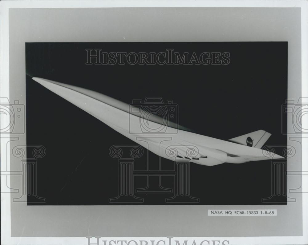
Art: a vintage lithograph of the Lockheed L-2000 SST in flight, w/3 view on the back.

Document: “CT-39 International Sabreliner,” a Rockwell International booklet/brochure describing the multipurpose utility jet

Document: “Air Force Expeditionary Catapult,” a truly massive billet of paper serving as a proposal from the All American Engineering Company for the System 300 Catapult, 1955. This was to be a turbojet-powered cable launching system for jet fighters which could be easily transported and set up in the field. (NOTE: this one counts as two reports, as it’s fairly gigantic)

Document: Aeroassisted Flight Experiment Nonadvocate Review, 1989, NASA

Document: Pocket Data for Rocket Engines, 1953, Bell

Document: SAM-D Air Defense Weapon System, 1973, US Army

Document: Pilots Handbook of Operation XLR11-RM-3 & XLR11-RM-5, liquid Rocket Engines, 1950, Reaction Motors

Art: X-15 lithograph (date unknown)

Document: The Centaur Program, 1961, Convair

Document: Orbiter Vehicle Structures, Rockwell

Document: An integrated Moonmobile-Spacesuit Concept, 1961, Aerojet

Document: The Intercontinental Stratoliner 707-320, 1955, Boeing

Document: Douglas DC-8 Design Study, 1953, Douglas

Document: Transport Weight Comparison Based on Lockheed 49-10, 1943, Lockheed

Document: ETR Launch Operations Plan for Cenaur on Shuttle, 1979, General Dynamics

Diagram: MD-11 wing diagram, six-feet long: McDonnel-Douglas, 1995

Document: A Lockheed presentation on the GL-224 Turbo-Jet VTOL Aircraft, 1958

Document: A Project RAND report on the GG-2 all-wing bomber, 1949

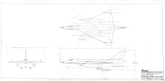
Document: A small Rockwell brochure on the “common core” concept for a fixed-wing subsonic B-1 variant, 1979 4) A presentation on the Douglas “Skybus,” 1944

Document: A NAA report on a turboprop-powered F-82E for ground attack, 1949

Document: A Curtis report on the twin engined F-87C, 1948

Document: A Vertol report on VTOL transport aircraft, showing several very different configurations, 1956

Document: A Lockheed presentation to the AIAA on the history of the Fleet Ballistic Missile, 1978

Document: A collection of Manned Spacecraft Center Space Shuttle orbiter concepts, 1972

Document: A Convair collection of design drawings of an Assault Seaplane, 1948 (NOTE: this one counts as two reports, as it’s fairly gigantic)

Document: A Vought report on the Regulus II missile with detailed diagrams, 1955

 Posted by at 3:41 pm
Jul 202014
 

I’m about $21 short of the next milestone, which will result in two “PDF reviews” per month of little-known online aerospace history resources. So if that idea appeals… consider signing up (and telling all your friends who have a few dimes to rub together).

Also: in August there will be three documents/large format diagrams released, along with three CAD diagrams. The documents/LFD’s are yet to be chosen (the $10 patron will get to vote on this in the next week or so), but the CAD diagrams are underway. One is already basically complete: the first accurate and clean, large 3-view diagram of the Northrop Tacit Blue demonstrator. The second will be of a proposed launch vehicle. The third is still up in the air.

 
patreon

 Posted by at 1:13 pm
Jul 182014
 

A while back I took a stab at printing cyanotype blueprints on canvas (the kind used by artists for painting on). After a rough start, I managed to get the process to work pretty well. It’s more complex and substantially more expensive than cyanotype printing on vellum paper, so I don’t know if I’ll make canvas blueprints available for regular sale like the paper versions. Still, I’ve put the first three successes on ebay if anyone is interested:

“Little Boy” atom bomb blueprint on canvas

WP_20140718_004 WP_20140718_005 WP_20140718_006

“Fat Man” atom bomb blueprint on canvas

WP_20140718_007 WP_20140718_008 WP_20140718_009

Dual Saturn V blueprint on canvas

WP_20140718_001 WP_20140718_002 WP_20140718_003

 Posted by at 10:48 am
Jul 162014
 

The “Firefly α” (“Firefly Alpha“) is a proposed small expendable launch vehicle, payload 400 kilograms. What is supposed to set the design apart:

1) Methane for fuel

2) A plug cluster first stage engine

fireflya-rocket-20140619230514

Methane has been repeatedly proposed over the decades for boosters, but it has never been used. It has higher Isp than kerosene and similar heavy hydrocarbons, but at the expense of low density and being cryogenic.

The plug cluster engine has also often been proposed. The idea: take a large number of small rocket engines and arrange them in a circle (well, as close to a circle as you can get with a finite number of points). Instead of pointing them straight aft, point them ten or so degrees inwards, and put a “plug” in the middle of them. The rocket exhaust then expands against the plug. What you end up with is a simpler version of a toroidal aerospike. The advantage is that you don’t have to develop a really big engine, just a number of smaller ones; and your booster engine now has automatic altitude compensation. This can be a serious issue for first stage boosters; they lift off at sea level and can fly virtually to the vacuum of space, and a rocket engines performance is driven in no small part by how well it compensates for the surrounding atmospheric pressure. If the rocket nozzle it optimized for maximum vacuum performance, this means that the pressure in the exhaust as it expands through the widening nozzles, drops below atmospheric pressure at some point. This can not only rob the nozzle of performance, it can also collapse, crushed like a beer can hooked up to a vacuum pump. A nozzle optimized for sea level, which has the exhaust reach sea level pressure more or less right at the exit plane, works fine all the way to space, but there is a lot of wasted impulse. An aerospike or a plug cluster automatically compensates, so a properly designed engine gets best performance all the way.

image002-s-w350-h350-q75-m1404491167

The problem: that central plug gets *hot.* Hot enough that cooling is a major, heavy and expensive issue. Further: plug clusters only approximate true aerospikes. Performance can be kinda… meh. The illustrations of the FRE-1 engine look like the performance benefit of the central plug will be minor… the individual rockets have fairly substantial nozzles on them, while the plug only seems to contribute a fairly small additional amount due to its short length. A caveat: truncated plugs can benefit from “virtual” plugs, and that seems to be what’s going on here. If you inject a gas into the central portion of the plug, the rocket exhaust will pressurized said gas, pushing on the engine. The result is much as if you had an actual physical plug… but one you don’t have to worry about overheating. The way this is normally designed, the turbine exhaust from the pumps powering the engines is dumped into the center to for the gas-plug. A dandy way to use turbine exhaust gasses you were just going to dump overboard anyway. But the Firefly is a pressure fed system: the LOX and methane propellants are going to be allowed to boil in their tanks to provide the pressure needed to push the propellants into the engines. So… no turbine exhaust. No spare gasses at all, actually.

Also: autogenously pressurized system like this have another issue. By definition, the liquid propellants being pushed through the system are just a hairs breadth away from boiling. So when they pass through the rocket engin injectors and undergo a pressure drop… they boil. or simply flash straight to gas. If this happens in the combustion chamber… great! But the math shows that this wants to happen in the *injectors.* And what happens is that gas bubbles form in the tiny injector ports, mucking up the works. The easiest way to make sure this doesn’t happen is to carry along pressurant gas like helium. Most of the tank pressurization still comes from the cryogenic propellant boiling, but an additional few (dozen?) PSI are added by the helium. This gives the propellant just enough buffer to make sure it gets all the way through the injector before bubbles form.

themoreyouknow

 Posted by at 12:24 pm
Jul 102014
 

The first month of my Patreon thingie is up and running now. Available – until next month, when they’ll be replaced by the next set of stuff – are the following:

1) A large format diagram of the B/J-58, a Convair concept for a two-engine tactical B-58

2) A PDF document, “Manned Space Stations and Alternatives” which covers Gemini and Dyna Soar-based small MOL-like station concepts, and includes info on the Gemini satellite inspector/interceptor

3) Two CAD diagrams, one of the McDonnell-Douglas Model 192 ISINGLASS hypersonic rocket-powered recon platform, the other comparing the Titan IIIC with the Titan IIIC/Dyna Soar and the Titan IIIM/MOL.

If you’d be interested in helping me dig up and release this sort of obscure aerospace historical material, or if you want to get in on the rewards, please consider joining my Patreon.

patreon

2014-07 ad3 2014-07 ad2 2014-07 ad1

 Posted by at 1:17 am
Jul 062014
 

I thought these might interest some, even with the heavy-duty watermarks:

This one shows a Max Faget “DC-3”-type orbiter serving as the base of operations for some sort of repair or resupply using teleoperated robots. There was a lot of expectation of such devices being used with Shuttle in the early days, but they (so far) just haven’t proved to be as capable as a guy in a suit.

img0052Aimg0052B

————-

This one shows a nuclear rocket-powered manned Mars vehicle. It’s called a “nuclear powered space station” in the caption…


img0049Aimg0049B

———-

This image shows two “DC-3” type orbiters (they look like North American Rockwell designs to me) meeting up to build a single interplanetary probe mission. Neither shuttle was capable of lofting both the deep space booster and the payload, so two launches are required. Of course, this sort of thing never happened.

img0035Aimg0035B

—————–

This one shows another telerobot in action. The caption on the back says that it’s being used to check over the shuttle prior to re-entry, which doesn’t match the image… but might have been of interest for the crew of Columbia.

img0050Aimg0050B

————-

This shows a Boeing/Grumman TSTO Shuttle concept. The orbiter uses external propellant tanks; in these sort of designs, the tanks were usually all hydrogen. The much smaller volume of liquid oxygen would be kept in tanks that fit within the orbiter, and would of course come back. The reusable booster was necessarily gigantic.

img0019A

—————-

This one is kinda different: a plan for how astronaut David Scott was supposed to test the Astronaut Maneuvering Unit on Gemini VIII. This test was not carried out, since the spacecraft suffered a stuck valve on a thruster, went into a rapid tumble, nearly killed the crew and the mission was promptly aborted. The same sort of test was attempted on Gemini IX, and proved nearly as disastrous. Eugene Cernans space suit was specially made for the test, with an outer layer of woven steel “pants.” This was due to the fact that the AMU used hydrogen peroxide for propellant, exhausting superheated steam and oxygen exhaust. But the woven steel made the pressurized pants almost totally rigid, making the spacewalk back to the AMU a serious chore. As a result, his faceplate fogged up and he was nearly blind. He never got into the AMU, and it was never launched again. The Manned Maneuvering Unit tested on the Shuttle used cool pressurized nitrogen, negating the need for steel pants.

6673856 6673855

—————–

This one is, I believe, from the late 1970s and depicts a jetliner with a multitude of small turbofan engines along the trailing edge of the wing. The engines would deflect with the control surfaces, providing thrust vectoring for STOL flight.

htk3hb4t

——-

Finally, everyone’s favorite… a hypersonic transport. Designs like this one from 1968 tended to be powered by scramjets which, forty-plus years later we still haven’t gotten to work in any really meaningful way. Whoopee.

4266120

 Posted by at 12:27 am
Jul 042014
 

I have added another milestone to my Patreon campaign. If I get to $500 of patronage…

There are a lot of PDF (and Powerpoint) references available online that would be of interest to aerospace aficionados. But that’s kinda the problem: there are a *lot* of them. NASA alone has had millions of reports online. There are far too many for any one person to even try to get a handle on. However… I’ve got a handle on a great many of them. While they are – or in some cases were – freely available online, you’d have to know they existed first. Well… for many thousands of such reports… I know they exist. So at this milestone, I’ll post reviews, including illustrations, of two such reports or presentations per month. Additionally, I’ll post links to the reports or, in some cases, the reports themselves.

So rather than just some snipped images, you’ll get the images, a description of the report *and* the report itself, posted to the APR Blog. This is in addition to the reports, brochures, documents and diagrams that get sent to patrons, stuff that *isn’t* otherwise available.

patreon

 Posted by at 9:12 pm
Jul 042014
 

The photo archives of the Baltimore Sun newspaper is being sold off on eBay. A whole lot of really old glossies of every vaguely newsworthy subject… including rockets and spacecraft. Two which caught my eye are listed as “Dyna Soar” designs, but clearly aren’t. What they are is hard to discern. They have the look of late 50’s, early 60’s aerospace concept art, but the ships shown look a little too sci-fi to necessarily be products of the aerospace industry. Instead, they might be products of the *news* industry… someone wrote an article about the Dyna Soar, and someone at the Baltimore Sun – or perhaps the AP, LA Times or some other newscorp – painted these images, dreaming them up out of whole cloth. The certainly look “cool,” but I’m much less convinced that they look “practical.”

This one depicts what appears to be a glideback first stage, designed around the F-117’s stealth facetting principles. Those wingtips look like they aren’t long for this world, as they will almost certainly be banged into the runway. Actually, it looks like they project substantially lower than the aft landing skids, meaning that the wingtips will *necessarily* dig into the ground. No date given; however, it appears to have been associated with the following image, which dates from June, 1959.

ebay 2014-06-29 1

——————

This image shows a USAF vehicle of some type. Again it is described as “Dyna Soar,” but it clearly isn’t. It appears to be a four-jet-engine aircraft, probably a bomber; the wide, flat forward fuselage is a bit of a stumper.

baltimore sun photo 1

——————–

This one at least comes with good captioning, and is clearly an LA Times artist impression of a Dyna Soar vehicle based on a wind tunnel model.

ebay 2014-07-04 a

———————

They, especially the first two, are certainly interesting. But at $17 each, they’re a bit too rich for my blood. So if any of y’all pull the trigger and buy them, please keep me in mind if you take them near a scanner…


 Posted by at 9:59 am
Jun 302014
 

I have a pretty fair supply of interesting documents and large format drawings… but not an infinite supply. Consequently, I’m in the market. Do you have interesting aerospace (aircraft, missiles, spacecraft or even perhaps unusual naval or terrestrial projects) documents, large format diagrams or actual blueprints? If so, let’s talk. I’d like to borrow, rent or buy such things. My preference is of course for unbuilt projects, but basically *anything* interesting would be… interesting.

If you have something you’d be willing to share, but not give away, I’d be happy to scan it and send it back ASAP. Alternatively, I’d be happy with good scans.

Additionally: a lot of interesting stuff pops up on eBay. I am actively trolling eBay for such things; just bought two documents tonight. But there’s so much stuff on eBay, with such weird and divergent descriptions, that I can’t possibly hope to catch everything. So if you see something on eBay that looks interesting, by all means let me know.

 Posted by at 11:21 pm