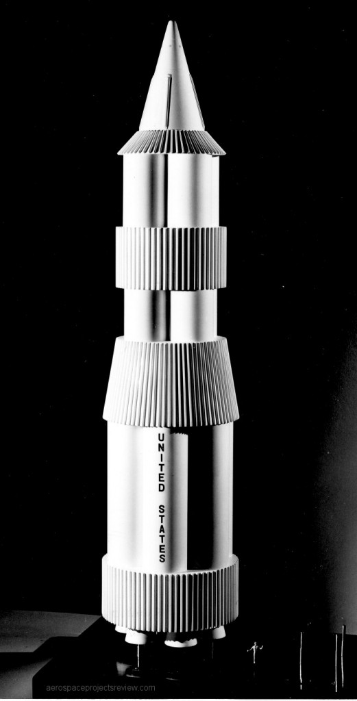
A photo of a NASA Nova design, in rather crude display model form.
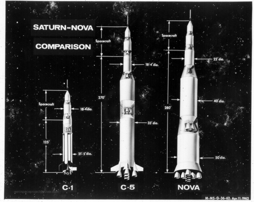
A 1962 NASA graphic showing the Saturn I, Saturn V and one or the more stereotypical of the Nova configurations to scale. Note that they all show direct-landing Apollo spacecraft… an extra stage, and no LEM. The Nova is similar to the “Saturn C-8” configuration. Note that the second stage of the Nova is larger in diameter and almost as long as the first stage of the Saturn C-5, and would have made the basis of a fairly substantial launch vehicle on it’s own.
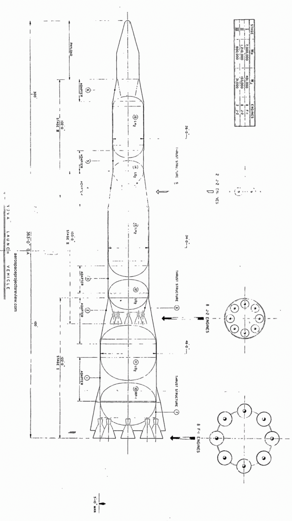
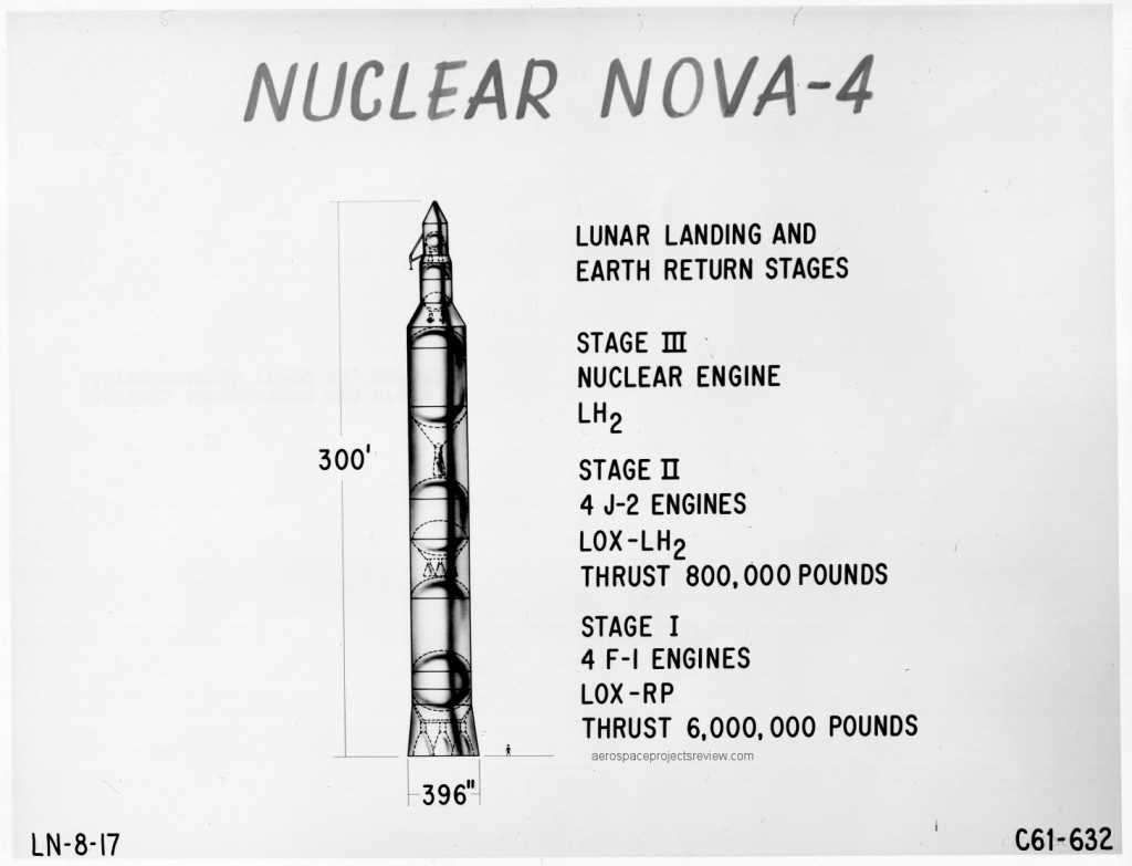
A NASA-Marshall concept for a Nova launch vehicle. Nova began life as a vehicle somewhat smaller and lower-capability than the Saturn V, and quickly grew substantially larger than the Saturn V, ending its run as the “Post Saturn” launch vehicle (with designs such as ROMBUS and Nexus). This design features eight F-1 engines on the first stage, and has been, probably apocryphally, referred to as the “Saturn C-8.”
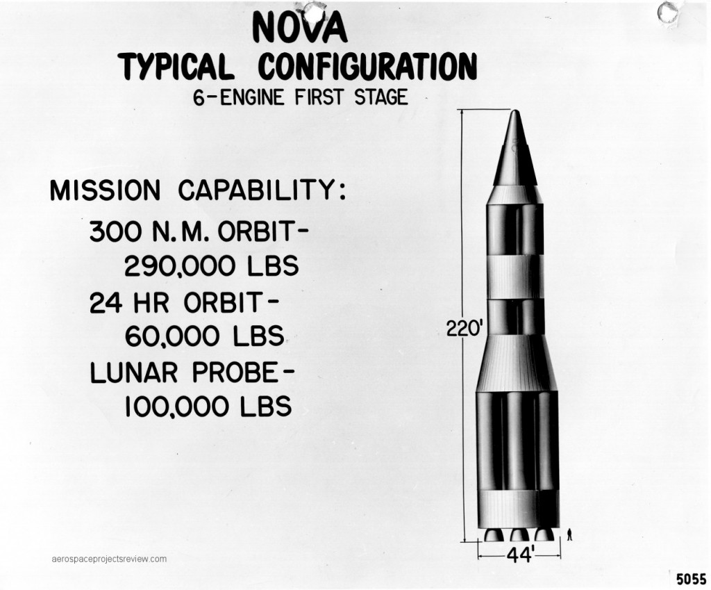
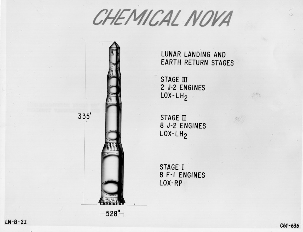
A piece of NASA presentation artwork from 1961 showing a basic design for an all-chemical-rocket design for a Nova launch vehicle. This would have been somewhat more powerful than the as-yet undesigned Saturn V; and it would have needed to be in order to carry of its mission. The Lunar Orbit Rendezvous design had not yet been chosen, and consequently the Apollo capsule and the service module both would have been landed directly on the lunar surface.
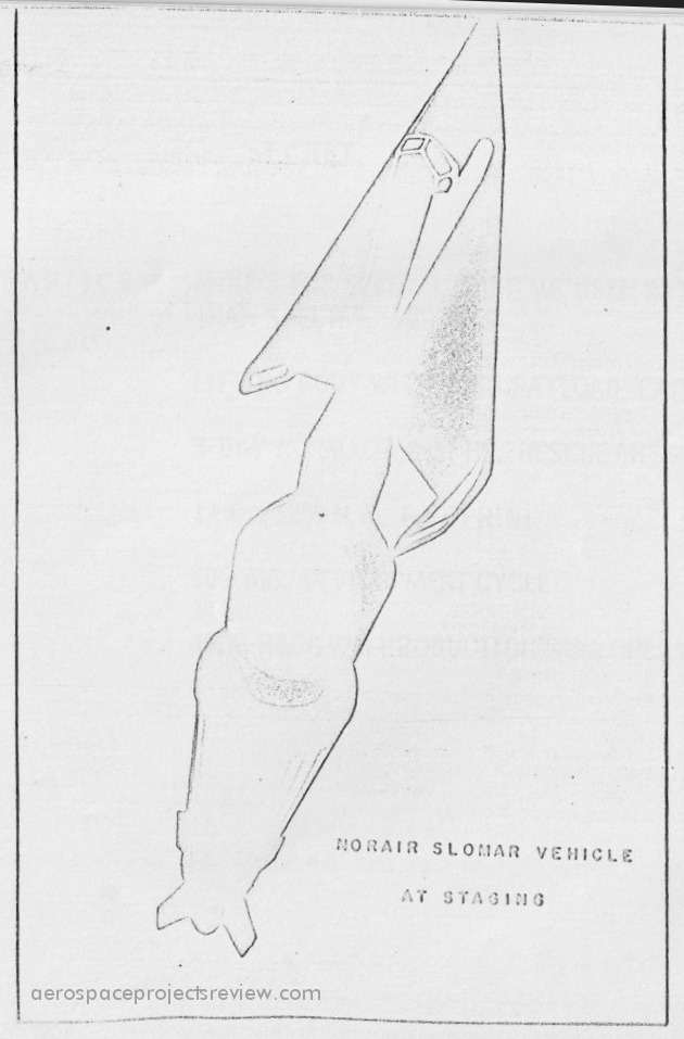
The quality is terrible, but apart from photos of a display model, this is the only illustration have of Northrop’s design for SLOMAR (Space LOgistics Maintenance And Rescue), a USAF program circa 1961 to study the sort of spacecraft that would be needed for crew and cargo transport to the space stations that everyone knew the USAF would have in some abundance by the end of the decade. The Northrop design is virtually identical in configuration to the Boeing Dyna Soar, though apparently a bit bigger.
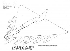
A 1959 Boeing concept for an airbreathing HTOL booster for Dyna Soar. Compared to the other pure-rocket VTO boosters, this would have been a monster… far bigger, far heavier, far, far more expensive. Which almost certainly explains why not only did such a booster not get serious study further down the line for Dyna Soar, it didn’t even rate detailed diagrams in the reports.
Staging would have been an interesting show.
NOTE: The isometric artwork for baseline concepts 4-7? Not available, sadly.
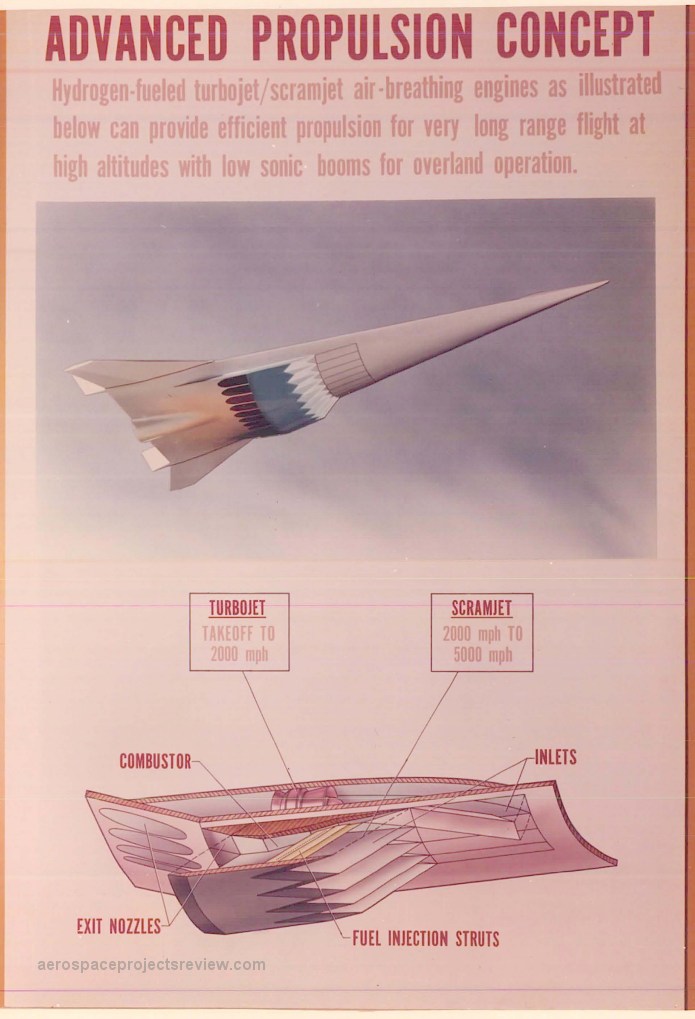
A piece of NASA-Langley artwork describing the future of aeropropulsion… the scramjet engine. The provenance on the art is hazy at best… found in the uncatalogued collection of a former Langley engineer, it probably dates to the mid 1960’s. The aircraft illustrated here has been seen from the early 1960s up into the late 1980s, so that at best brackets the art. The aircraft has been used as a hypersonic transport and as the first stage of a space launch system. As shown here, the model used was *probably* a wind tunnel model repainted and repurposed as a display model… none of the diagrams I’ve seen of it have included the “hump” on the underside of the aft expansion ramp. Most likely that’s the connection point for the support “sting” for tunnel use. Alternatively, it *could* represent a fairing for a rather sizable rocket engine, though that seems unlikely… during scramjet operation the hump would not only mess with exhaust flowfields, it would also be subjected toa whole lot of thermal unpleasantness.
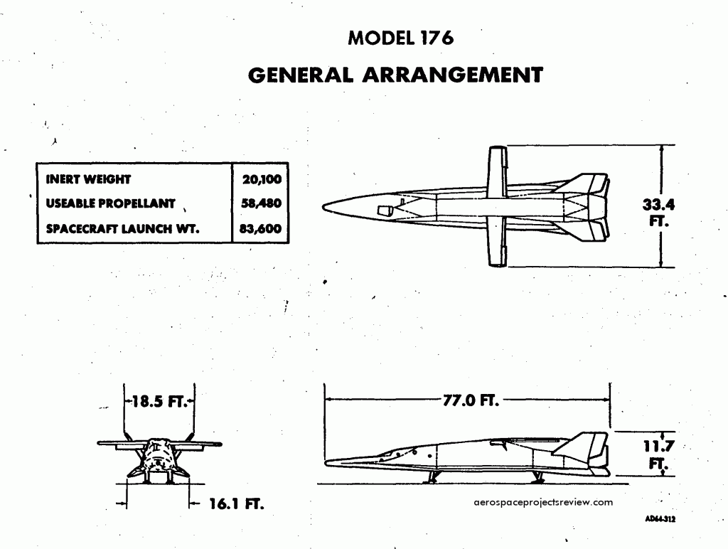
As of 1964, the GA of the Models 176, a lifting body, stowed-wing spaceplane. See HERE for late 1960’s artwork of a larger version.
