Jun 282014
 

I’ve launched the Patreon funding campaign:

http://www.patreon.com/user?u=197906

If you appreciate the aerospace research I do and the stuff I dig up, please consider contributing. As a bonus, you will get goodies if you do! High rez large format diagram scans, brochures, reports, proposals, etc.


Pledge $0.75 or more per month

You get my thanks and a warm fuzzy feeling, knowing that you are contributing to saving the history of aerospace engineering!

Pledge $1.50 or more per month

You will receive the uploaded documents and blueprints at 125 dpi

Pledge $3.00 or more per month

You will receive the uploaded documents and blueprints at 200 dpi

Pledge $4.00 or more per month

You will receive the uploaded documents and blueprints at 300 dpi

Pledge $5.00 or more per month

You will receive the uploaded documents and blueprints at 300 dpi plus a bonus CAD diagram at 300 dpi, sized for 8.5X11

Pledge $6.00 or more per month

You will receive the uploaded documents and blueprints at 300 dpi plus a bonus CAD diagram at 300 dpi sized for 11X17

Pledge $8.00 or more per month

You will receive the uploaded documents and blueprints at 300 dpi plus a bonus CAD diagram at 300 dpi sized for 18X24 or larger AND the diagram in the native vector format

Pledge $10.00 or more per month

You will receive all the prior rewards, plus have the opportunity to vote on what will be released next.

Tell all your friends.
 Posted by at 10:34 am
Jun 232014
 

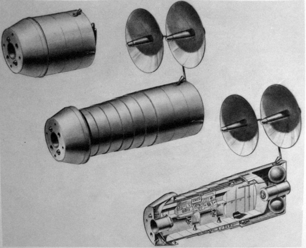
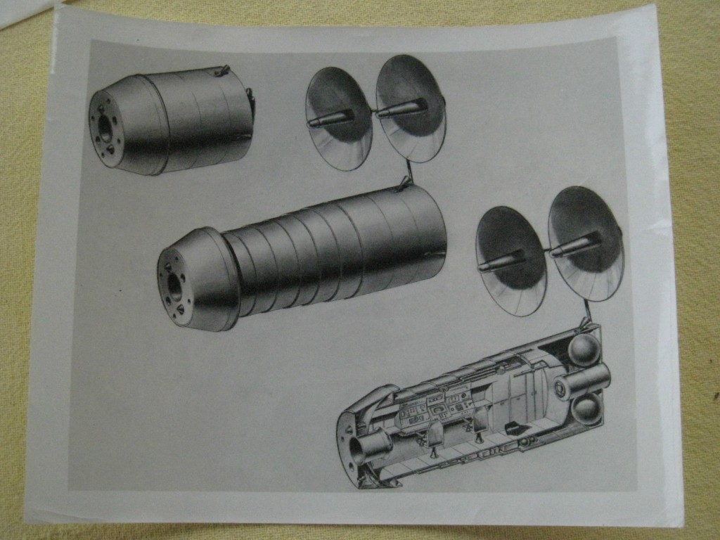
Saw this on eBay a while back. No further data. I assume it’s from the early/mid 1960’s, early MOL era. I don’t imagine that it was a particularly serious study; I’ve never seen it’s like elsewhere, and it seems like it would be quite heavy and prone to leaks. A reasonable guess would put the diameter at 10 feet, standard for the time (same diameter as the Titan II/TIIIc core vehicle).

extendable lab

I tinkered a bit to fix the warping and clean up the image:

extendable lab a

 Posted by at 6:08 pm
Jun 162014
 

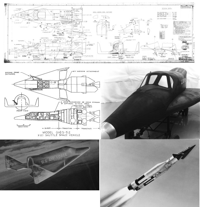
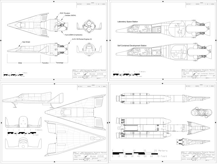
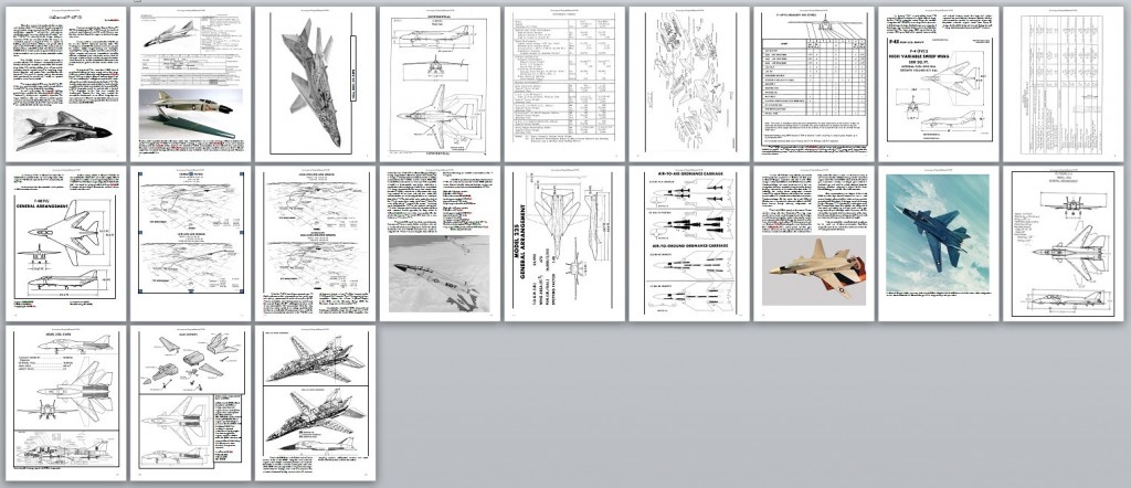
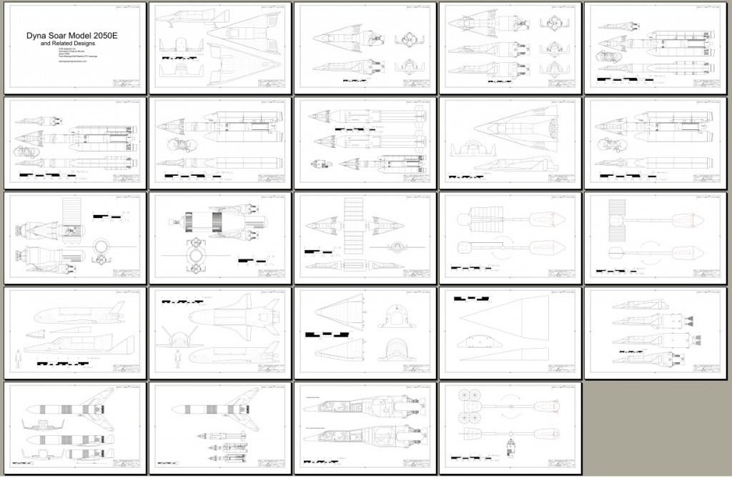
At last: Aerospace Projects Review issue V3N4 is available. This issue has 128 pages. The main article focuses on the Boeing Model 844-2050E, the final, almost-built version of the X-20 Dyna Soar spaceplane. Included are not only detailed diagrams showing the design and construction of the spaceplane, but also drawings and information on proposed operational versions, including passenger ferries, satellite inspectors/interceptors, even nuclear bomber versions.

Also included are a large number of all-new diagrams that finally show the Dyna Soar atop the Titan IIIC accurately and in detail, along with proposed variants, variant launch systems and suggested space stations.

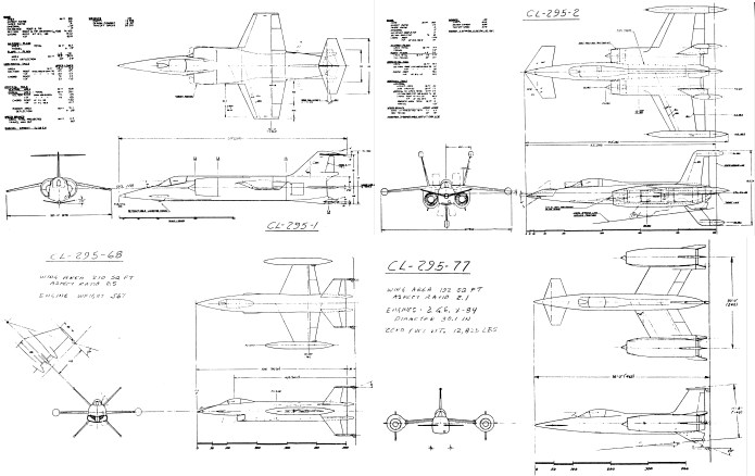
An article by Bill Slayton on the Lockheed CL-295 design series. This was a series of tailsitter VTOL fighters including designs derived from the F-104 as well as wholly new designs.

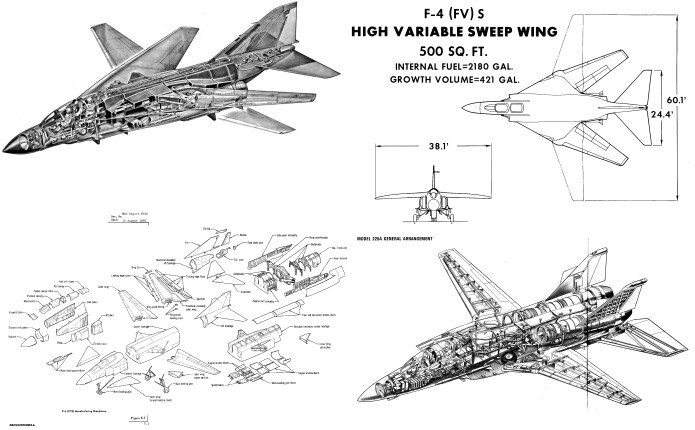
The third article is on the McDonnell F-4(FVS),a mid-1960’s concept to replace the low-mounted fixed wing of the F-4 Phantom II with an all-new variable geometry “swing wing.” The story goes from the F-4(FVS) in its numerous incarnations through the Model 225, McDonnell-Douglas’ entry into the 1968 US Navy VFX contest which resulted in the F-14.

Also, Aerospace History Nuggets on the US Navy SCAT VTOL and the Republic Aircraft RAC-730 SSTO aerospaceplane.

23 megabyte PDF file


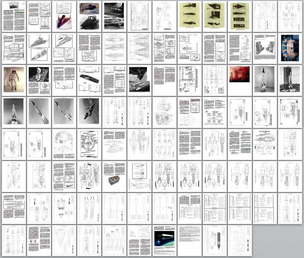
Here’s the complete issue V3N4 layout:

It is available in three formats. Firstly, it can be downloaded directly from me for the low, low price of $10.00. Second, it can be purchased as a professionally printed volume through Magcloud; third, it can be procured in both formats. To get the download, simply pay for it here through paypal.

——–


———

To get the printed version (or print + PDF version), visit my MagCloud page:

http://scottlowther.magcloud.com/

——————

Also available: the V3N4 Addendum. This contains 49 pages formatted for 11X17. Includes larger and improved versions of all the CAD diagrams produced for V3N4, as well as larger versions of some of the illustrations from the X-20 and F-4(FVS) articles (as well as a number of illustrations that did not appear in the X-20 article):

The V3N4 Addendum can be downloaded for only $4.00!
——–


———

 Posted by at 6:07 pm
Jun 082014
 

I’m getting close to being done with this one. The main article, clearly, is the one on the Model 2050E Dyna Soar, the second far smaller article is on the McDonnell F-4(FVS) and derivatives, the third is the old Bill Slayton CL-295 article from the original version of APR. There will be a few more small pieces, not shown here.

v3n4 ds2050e v3n4 cl295 v3n4 f4fvs

Issue V3N5 will almost certainly be smaller than this. Apart from the Lunar Gemini article, it will likely be composed of a number of all-new smaller articles. I’d like to move forward a short article from further down the run to this one, due to having some new info, but that info is embargoed by the source till later in the year. It’d be nice to get back on the two-month schedule for APR, but I wouldn’t hold my breath on that.

 Posted by at 1:13 am
May 072014
 

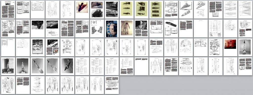
Slowing plugging away on the greatly revised X-20 Dyna Soar article. Shown below is what it currently looks like… something of a mess. There are still a great many more illustrations I want to add, including a bucket of my own CAD diagrams, but how many will end up here is uncertain. It’s already pushing 100 pages when you include the CAD diagrams; probably too big. Perhaps a later stand-alone version will have everything plus the kitchen sink…

Image306

And the CAD diagrams:

x-20-booklet-2014-03

 Posted by at 9:25 pm
May 072014
 

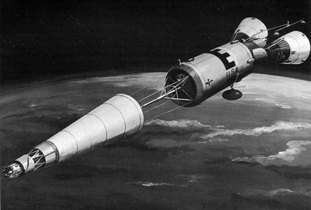
A mid-1960’s concept from General Electric showing a Manned orbital Laboratory-type space lab with two docked Gemini capsules and one nuclear reactor for power. Derived from the SNAP-10a system, this powerplant featured a small reactor at the apex of the cone; the cone itself is the radiator for the system. The SNAP-10a was not a spectacularly efficient system… it produced around 30 kilowatts of thermal energy, of which only 500 were converted to electricity. The system shown below would have been a larger, more powerful and hopefully more efficient system.

The small compact and busy-looking item on the far left of the image would have been the reactor itself. Between that and the structural truss work connected to the large radiator was a thick radiation shield, composed of something like tungsten. Even with this massive chunk in the way, the reactor was still segregated far away from the crew.

ge nuke space station

 Posted by at 12:34 pm
Feb 102014
 

For the next few days blogging might be a bit sparse as I work on the next issues of Aerospace Projects Review and US Bomber Projects. Usually when I release one of these, I get a *few* emails, generally complementary, sometimes asking for clarification or pointing out editing/spelling errors, that sort of thing (and with APR, “make go more faster”). I very rarely get “why don’t you include this” or “why don’t you do that” messages. Well… discuss. What would you like to see new and/or different in APR and/or USBP?

Also: the perpetual problem I have with both of these is lack of public knowledge of these titles. Heck, when I did “The Space Show” interview two months ago, I expected a slight bump in business… but sales (and views of the APR blog) actually went *down* slightly in the week afterwards. Damned if I can figure that out. So if anyone has any suggestions on how to get some press for these little endeavors, I’d appreciate ’em. And of course, an increase in interest & sales will mean an increase on *my* part in producing these things faster, so if you want APR and USBP issues at a faster clip, here’s how to get it done.

 Posted by at 6:53 pm
Oct 292013
 

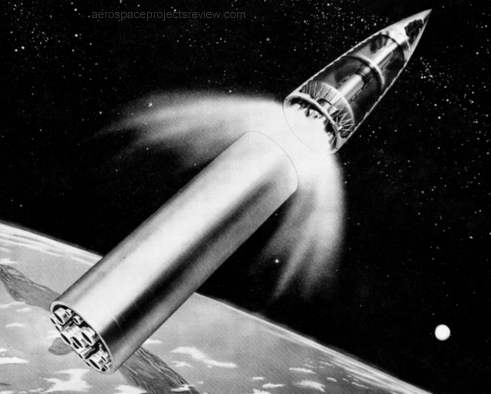
Artwork of a three-stage rocket designed by Krafft Ehricke around 1953. 126 feet tall, it would be capable of orbiting 11,000 pounds of payload into a 600 mile circular orbit. Liftoff weight would be 1.3 million pounds.

The first stage, here being shown dropped, would be parachute recovered. the second stage would be expended; the third stage would be used to built up a space station. If you can’t immediately tell where stage 2 ends and stage 3 begins, it’s because stage 3 is the central cylinder, with stage 2 being wrapped around it. This sort of staging arrangement was considered fairly often in the days before they actually had to build these things.

It would be able to land 3,000 pounds on the moon or shoot 5,000 pound probes past Mars or Venus.

 Posted by at 3:02 pm
Sep 252013
 

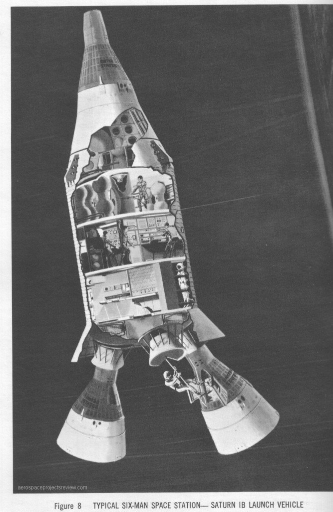
Also published in Lockheed Horizons, this design was meant for launch atop a Saturn Ib. It *may* have been part of the Manned Orbiting Research Lab studies. The Gemini logistics craft appear to be minimally modified.

 Posted by at 12:52 pm
Sep 232013
 

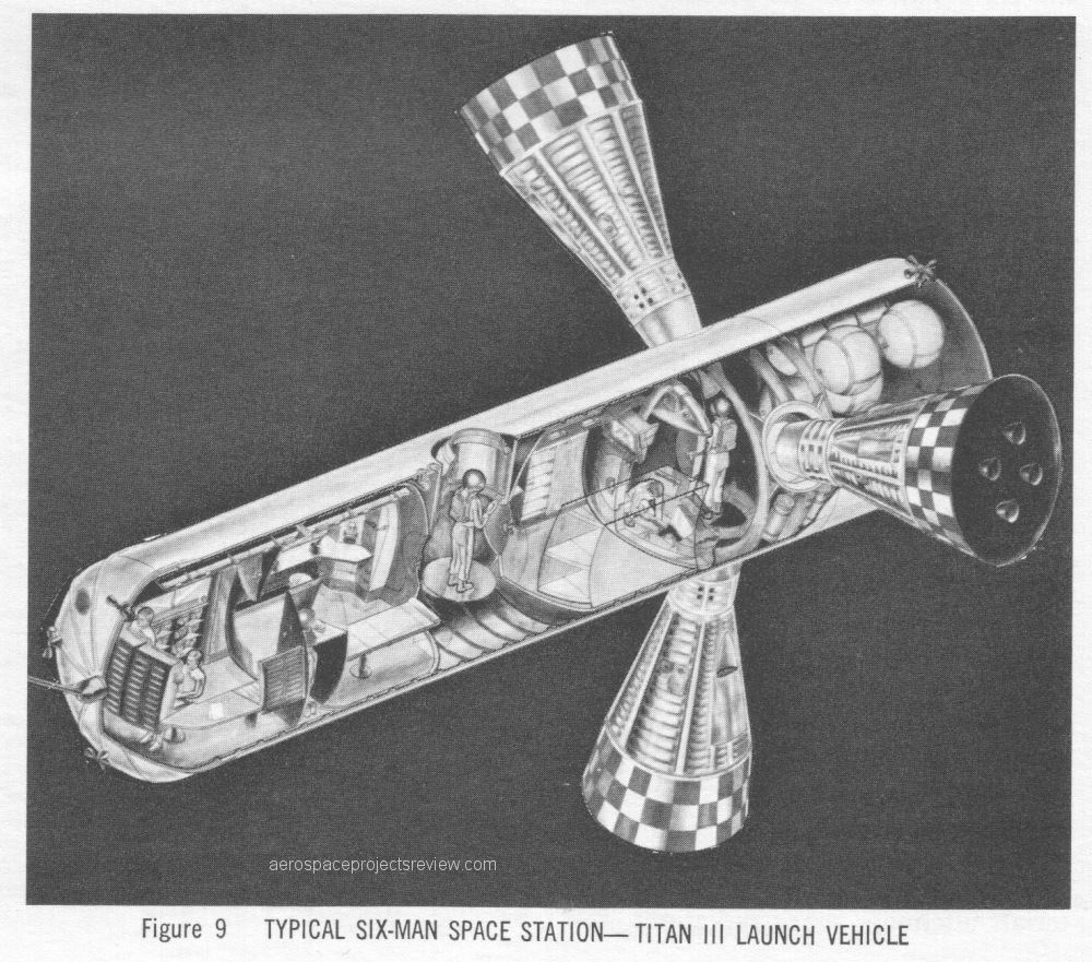
Artwork from the 1960’s (latter half of the decade) depicting a six-man space station. This was published in “Lockheed Horizons,” so almost certainly depicts a Lockheed concept. it is shown being services by Gemini-derived logistics craft. While these were McDonnell vehicles, Lockheed really didn’t have an important space logistics craft of their own in design, so they didn’t have much choice in the matter but to use either the McDonnell Gemini or the North American Apollo.

This design is clear similar to the Manned Orbital Laboratory. Like the MOL, this design was meant for launch atop a Titan III. Length uncertain, but diameter would be about 10 feet.

 Posted by at 10:51 pm