Jun 282016
 

NOTE: Not the best photos, but… ehh, what’re ya gonna do…

Dsc_3632

I have a new batch of physical media… digital prints and old-school cyanotype blueprints. What sets these apart is that they are BIG.

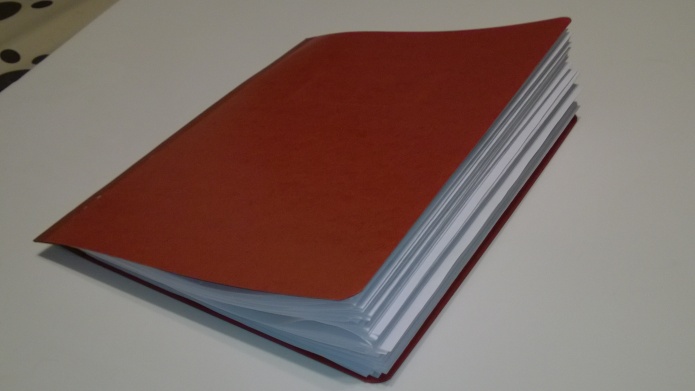
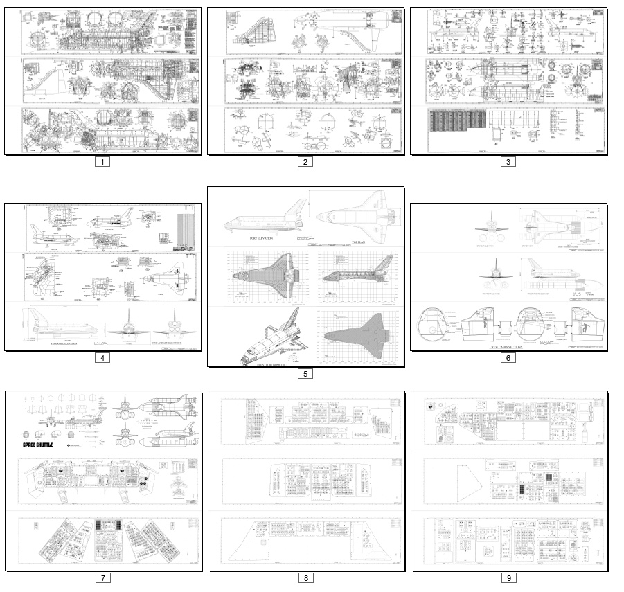
First, a book: Space Transportation System Diagrams. This is a collection of 27 wide format (the standard 11 inches high… but up to *40* inches wide) Space Shuttle diagrams. They are all official NASA.industry diagrams, painstakingly cleaned, depicting all aspects of the STS. Includes numerous instrument panel diagrams as well as structural arrangements, general arrangements, insulation/tile layouts, etc. This is available for $75. Ten were printed. NOW SOLD OUT

WP_20160628_055 WP_20160628_056 WP_20160628_054

bigbook_of_shuttle_diagrams

STS Diagrams book: $75


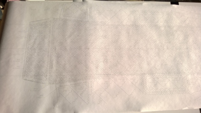
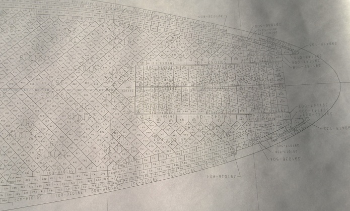
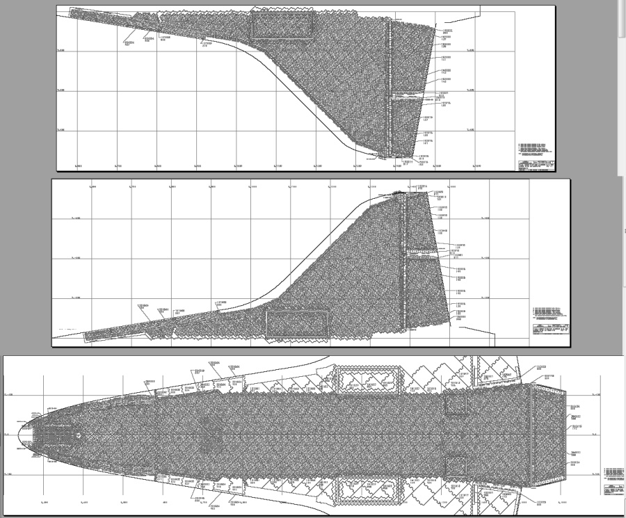
Second, some very large digital prints of the Shuttle orbiter underside tile maps. Three maps provided… left wing, right wing and fuselage. They are all 20 inches high, with the centerline diagram being about 80 inches long. Shows you where every tile goes, all for only $30. This has sold out. If you are interested, send me an email and I’ll let you know when/if more are made available.

WP_20160628_061 WP_20160628_060

tile_maps


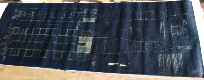
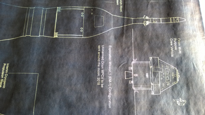
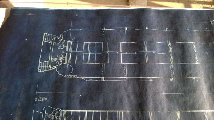
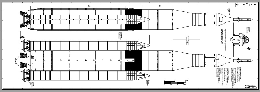
Third: 1/72 scale cyanotype blueprints, handmade, of the Space Launch System Block 1 launch vehicle. This blueprint is 24 inches wide by about 67 inches long, based on a CAD layout of my own creation and is available for $80.

WP_20160628_057 WP_20160628_058 WP_20160628_059

SLS_22.5X65.5

1/72 SLS Cyanotype Blueprint: $80


All of these are likely going to be available for only a limited time. I’ve had ten copies of the STS Diagram Book printed; each is individually numbered. So far, one sold. The 1/72 SLS is also likely to be only  limited print run; while undeniably awesome, it is kinda big, and I think I’d do better to replace the 1/72 diagram with a 1/144 version. So snap ’em up fast before they become collectors items!

As always with physical items, postage is required. A single flat fee is charged no matter how many items… if you’re in the US, you pay $10 in postage is you order one item or a dozen (so order a dozen). Elsewhere… costs a little more.

US postage: $10
Non-US postage: $18

 Posted by at 1:05 pm
Jun 222016
 

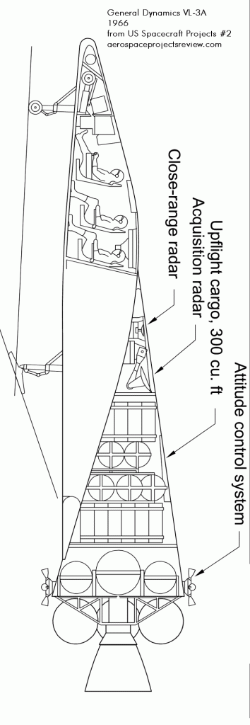
A General Dynamics concept for a logistics spacecraft (personnel and cargo transfer to/from space stations) from 1966. The VL-3A was a narrow lifting body design to be launched by a Titan IIIc, and featured flip-out wings and turbojets for runway landings. The VL-3A and other spaceplanes were presented in US Spacecraft Projects #2.

ussp 02-06-3

 Posted by at 9:34 am
Jun 132016
 

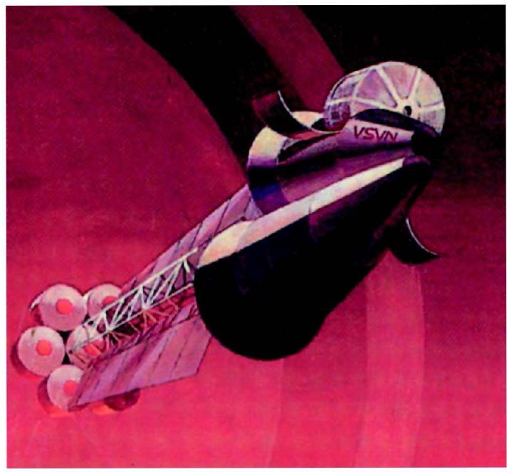
A piece of artwork yanked out of a Russian book, attributed to Rockwell. This appears to show a Mars-bound (or perhaps Mars-orbiting) spacecraft equipped with two biconic entry vehicles. The long truss structure and radiators would indicate a nuclear powered vehicle, presumably NERVA.

rockwell mars art

 Posted by at 10:28 am
May 162016
 

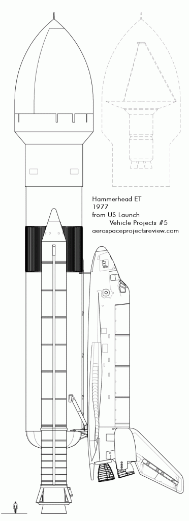
A 1977 Rockwell concept for how to expand the utility of the Shuttle system: move the payload from the Orbiter and put it in a shroud ahead of the External Tank. This would have allowed for much larger-diameter payloads to be carried. The ET would of course have had to go into orbit with the Orbiter itself. More info and diagrams of this are in US Launch Vehicle Projects issue 1.

uslp 01-07-1

 Posted by at 9:24 pm
May 162016
 

From back when General Motors was studying spacecraft, here’s an early 1960’s video showing tests of three means of surface propulsion for lunar vehicles:

The Archimedes Screw system was interesting, but it seems to me that there’s virtually no chance that it would be a good idea on the moon. The rough, razor-sharp regolith would seem likely to sandblast those shiny metal screws in little short of no time.

 Posted by at 12:40 am
May 072016
 

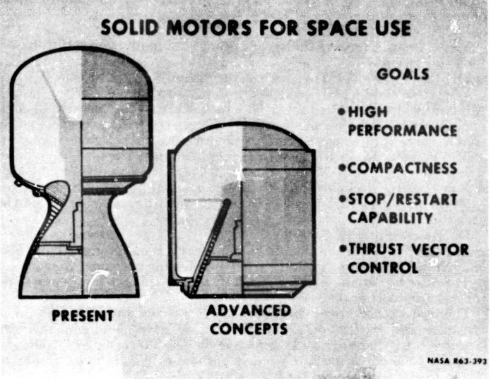
A NASA illustration of an advanced solid rocket motor concept, dated 1963. The most obvious difference between the “present” and “advanced” design was the buried nozzle. By properly shaping the solid propellant grain, the motor would perform normally but with a minimum of unused internal volume; this allowed the motor to be substantially shorter than the conventional design. This would make the associated interstage section equivalently shorter, lighter and cheaper. And by shortening and lightening the interstage, the launch vehicle would be shorter, lighter and stronger, with slightly sturdier structural dynamics.

advanced motor

The advantages of a more compact motor like this are pretty obvious. The disadvantages, maybe less so. The most apparent disadvantage is the *need* for far more advanced materials. That buried rocket nozzle is shown to be quite thin, thinner than the “present” design, yet it would be subjected to horrifying heating rates on *both* sides. There are few materials that could withstand that and retain any sort of structural strength.

Additionally: the desire is shown for thrust vectoring. Numerous options for that are available for the conventional nozzle… but it would be much harder with a buried nozzle. It might be easiest to simply gimbal the entire motor. Stop/restart capability has been achieved with solid rockets, but neither design show here provides for that. It is a non-trivial feature.

The igniter is show to be a small rocket motor suspended within the nozzle, directing it’s exhaust forward into the bore volume of the main motor. Variations on this sort of igniter are quite common for relatively short and stubby upper stage motors such as these.

 Posted by at 12:03 am
May 012016
 

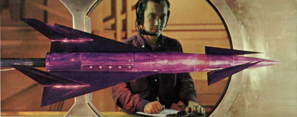
A photo of a NASA wind tunnel model of a hypersonic aircraft configuration. The circa 1960 NASA brochure (promoting the organization to college students) that included this provided no further information, but I’m reasonably sure I’ve seen the wind tunnel test report on this, calling it a reusable booster or reusable launch vehicle. If that’s the case, the upper stages and payload were *probably* going to be carried on the things back.

RLV

 Posted by at 8:00 pm
Apr 162016
 

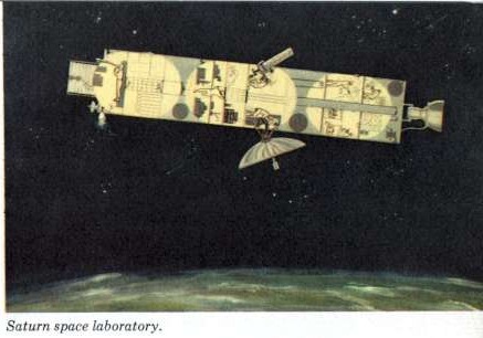
A sadly tiny illustration of a “Saturn Space Laboratory” from a circa 1960 NASA brochure (promoting the organization to college students). This looks like something halfway between MOL and Skylab; three pressurized modules in a “wet lab” space station. Diameter looks to be 10 feet, same as the Titan booster; early concepts for the Saturn called for the use of the Titan first stage to be the second stage of the Saturn I, with the second stage of the Titan being the third stage of the Saturn. This may well represent a Titan I or II first stage/Saturn I second stage as a space lab.

Given the entertainingly toxic nature of the Titan II propellants, I’d guess this was an earlier Titan I-based concept.

satur space lab

 Posted by at 11:49 am
Mar 292016
 

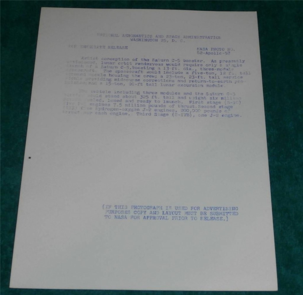
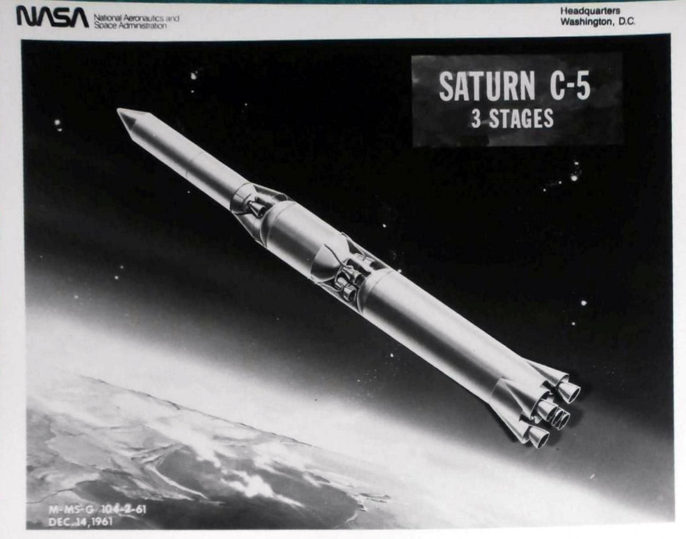
Some photos (from ebay) of a NASA PR glossy from December, 1961, showing the then-current Saturn C-5 configuration. Note the fairly obvious signs of some retouching of the engines on the first stage… either the engines were originally larger, or they were larger in number. Note the lack of the small but distinctive stabilizing fins on the first stage.

saturn c5 3 stages 2 saturn c5 3 stages

 Posted by at 8:44 am
Mar 032016
 

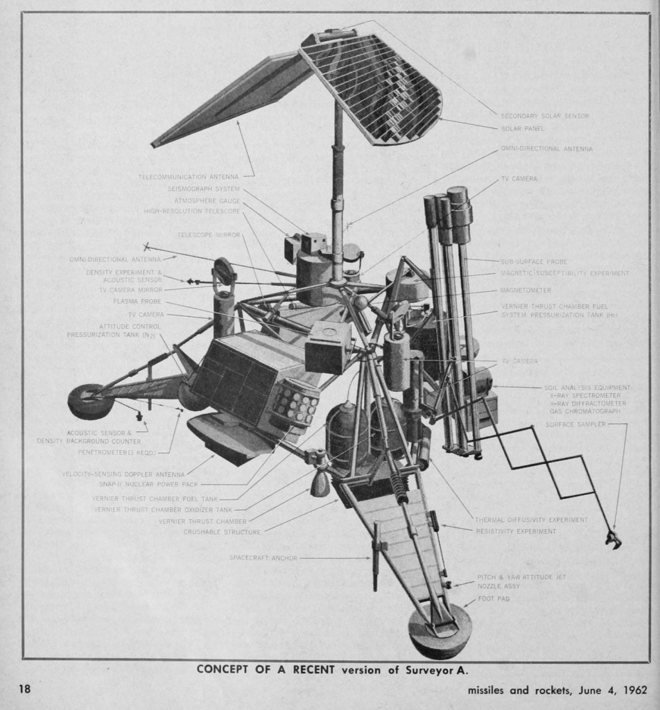
Artwork depicting the Surveyor lunar probe as of June, 1962. Reasonably close to the final product, but some differences are visible. The subsurface probe I believe was not employed; neither was the SNAP-11 nuclear power source. That was intended to power the lander through the lunar night.

missilesrockets1011unse_0270

 Posted by at 12:19 pm