Aug 052014
 

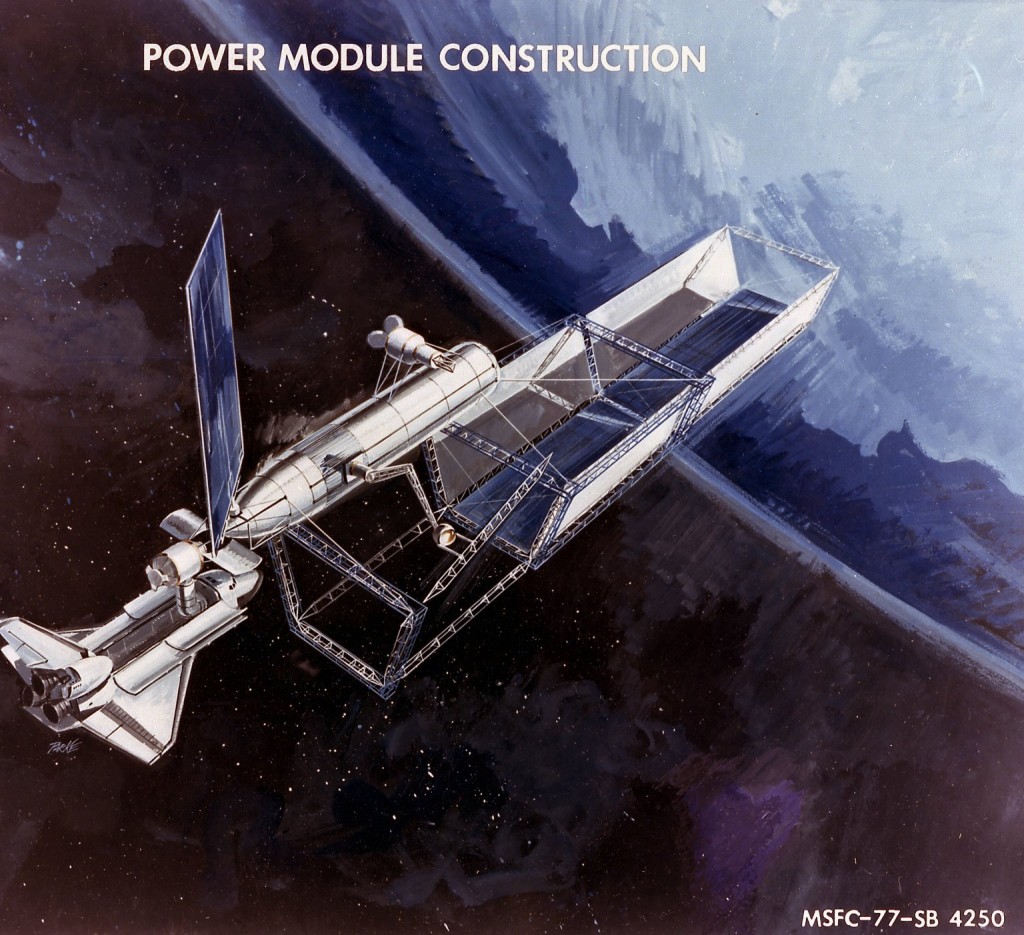
A NASA artists concept from 1977 showing the construction in low Earth orbit of a Power Module. This would be one of a *vast* number to be assembled; when finished they would be hauled up to geosynchronous orbit there to be assembled together into very large Solar Power Satellites. This design is shaped like a trough, with the bottom of the trough covered in photovoltaic cells; the sides of the trough would probably be extremely thin aluminum foil. The foil would reflect more sunlight onto the cells. This was done because thin aluminum is a whole lot cheaper *and* lighter weight than solar cells; additionally, these cells tend to operate slightly more efficiently at higher insolation levels (i.e. the more sunlight they get, the better they work).

This painting shows a Shuttle External Tank being used as the backbone of a Power Module construction base. At the nose of the ET is a small “Space Lab” for crew (with possibly more crew space within the LOX tank), and a large solar panel for power. Further down the side of the ET is a movable manipulator arm; at the end of the arm is what appears to be a manned pod which serves as the “hand.” The arm appears to have rails that run the length of the ET, allowing it to slide back as forth as needed. Further down the ET is the “beam builder,” a self-contained little factory that takes rolls of aluminum “tape” (the two “Mickey Mouse ears” on the back of the device) and forms and spot-welds the tape into large structural elements.

powermodule

 Posted by at 10:08 am
Aug 022014
 

Thanks to the funding made available via my Patreon campaign, these recently arrived:

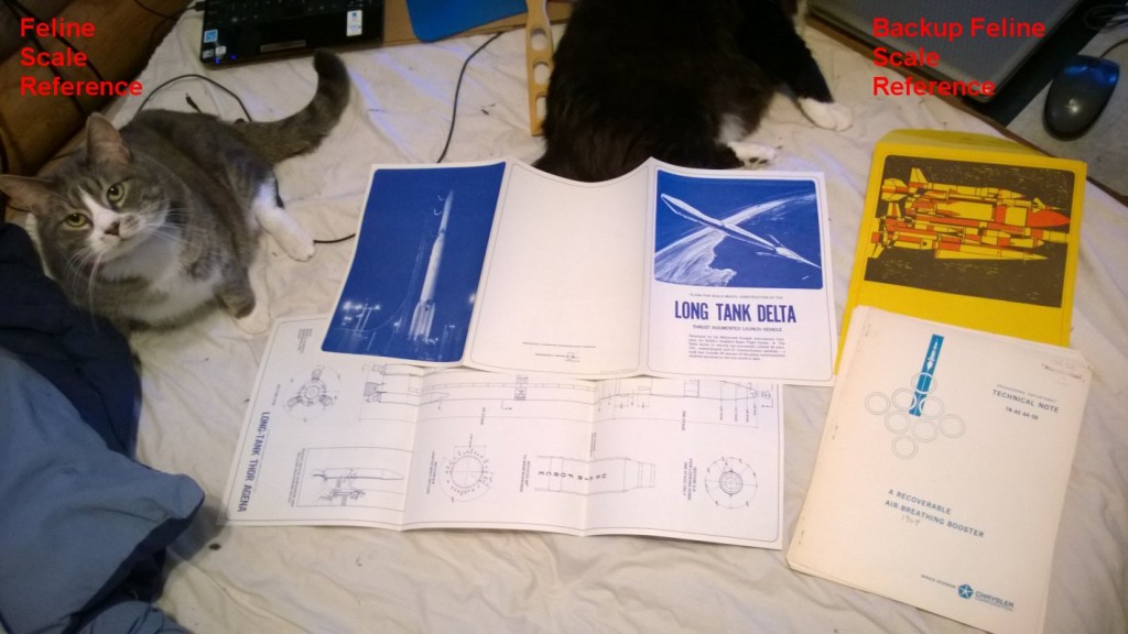
Document: “A Recoverable Air-Breathing Booster,” 1964, Chrysler Space Division. This report describes a ring to be fitted to the base of a Saturn I booster; the ring is equipped with either 4 or 8 additional H-1 rocket engines for additional liftoff thrust, as well as a similar number of turbojets to be used to return the ring-booster to Cape Canaveral for a vertical landing.

Diagrams: “Plans for Scale Model Construction of the LONG TANK DELTA” and “Plans for Scale Model Construction of the LONG-TANK THOR AGENA,” from McDonnell-Douglas, 1971. These came in an envelope, and illustration on which depicts the Delta rocket, the Honest John (the diagram of which I have previously obtained), the Saturn I, the Genie AAM, the Nike Ajax and the Nike Hercules. If anyone knows of the latter 4, please enlighten  me.

These will be added to the list of drawings/documents available to my Patreon patrons to vote on.

WP_20140801_006

patreon-200

 Posted by at 3:55 pm
Jul 302014
 

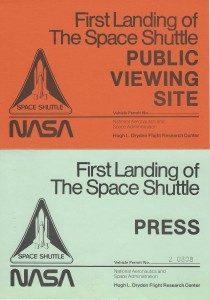
Two passes – Public and Press – for parking to witness the landing of the first Space Shuttle orbital flight, STS-1. The government threat/verbiage on the back is a little creepifyin’ but I’m pretty sure it’s expired by now (probably expired the moment it landed). These passes were scanned at 300 DPI and are presented half-rez.

shuttlepass1half shuttlepass2half 

These passes were obtained via an eBay purchase, and were “extras” to the items I was actually after (detailed large format diagrams of the Shuttle flight instrumentation). This purchase was made possible by my Patreon contributors. So if you like this sort of thing, please consider contributing to my Patreon campaign. Every little bit helps! The full-rez scans are available to all Patreon contributors.


patreon

 Posted by at 1:19 pm
Jul 292014
 

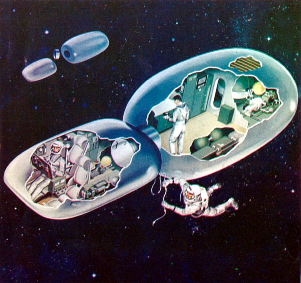
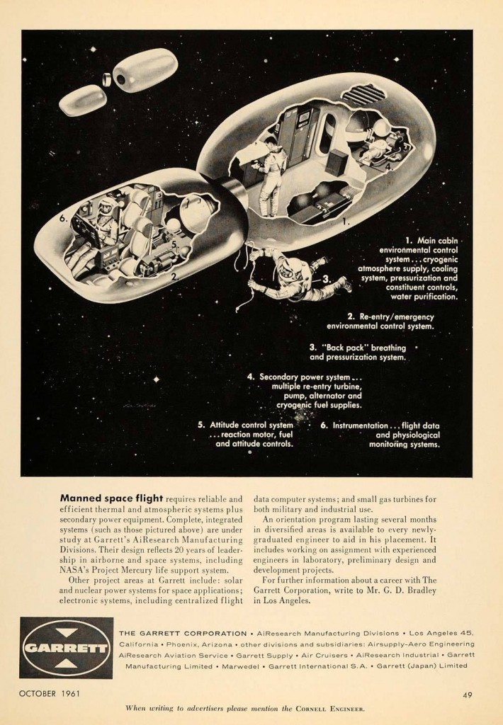
Found on the back of a 1963 issue of “Space World” magazine was this piece of artwork depicting an unusual – and perhaps fanciful – spacecraft. The same artwork had appeared earlier – at least as far back as 1961 – in a magazine ad for the Garrett AiResearch corporation. The artwork was thus *probably* created in-house at Garrett. Since Garrett was a manufacturer of turboprop engines and electronics, not an aircraft or spacecraft design firm, this is unlikely to have been a serious engineering effort. Still, it’s interesting to see what level of *apparent* effort the PR divisions of numerous companies went to back in the glory days of the Space Age.

spaceworld63ad


garrett

 Posted by at 12:24 pm
Jul 272014
 

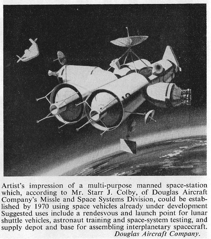
A 1963 Douglas concept for a space station. This one appears to have everything… to the right, the (Douglas-built) S-IV stage; to the left the (Douglas built) S-IVb stage; docked and coming in to dock, the (Douglas designed) ASTRO spaceplane. All mounted to a core space station that appears to be based on the S-II upper stage.

douglas station63

 Posted by at 1:20 pm
Jul 262014
 

I’ve cut the prices on all my cyanotypes by at least 25%, up to 40%. I’ve also gotten rid of the watercolor versions; it’s all vellum paper now (not only is it more historically accurate, it’s also a lot easier to process and ship).

So… take a look.

Cyanotype Blueprints

 Posted by at 1:44 am
Jul 232014
 

NOTE: this is the first official “PDF Review.” The idea is to present interesting online resources for those interested in  the sort of aerospace oddities that you can find in the pages of Aerospace projects Review. This little project is supported through my Patreon campaign; at current levels, I’ll post two such reviews per month. If you’d like to see more, or just want to contribute to help me along, please consider becoming a patron.

——————-

Dynamic tow maneuver orbital launch technique

US Patent 8,727,264

Direct link to PDF

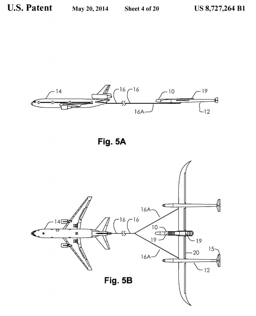
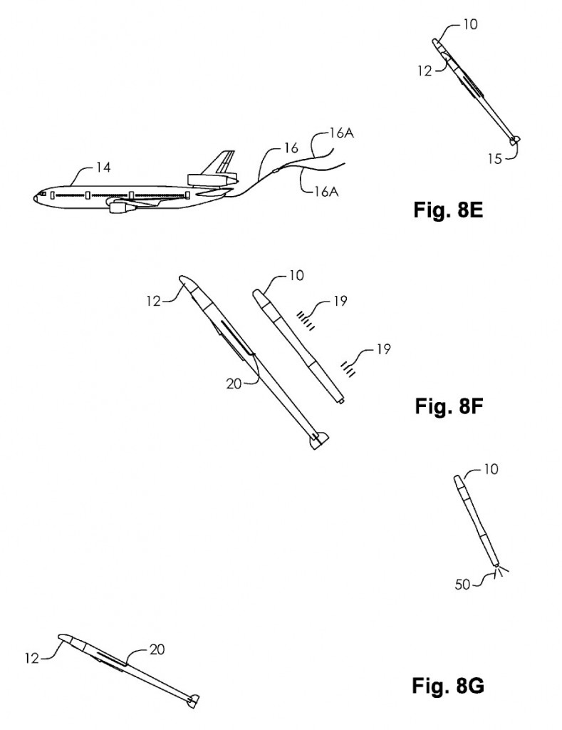
Filed in June, 2013, and issued in May, 2014, this patent granted to Burt Rutan describes an unconventional space launch system. An otherwise more-or-less conventional space launch rocket – the standard propellant-filled cylinder with a payload shroud up front and a rocket engine in the tail – is carried aloft via aircraft. This basic notion has been proposed, designed and enacted many times, from the US Navy’s NOTSNIK of the very late 1950’s to Minuteman ICBM launched from the C-5 Galaxy in the 1970s to numerous space launch proposals over the years. But this one differs in that the carrier aircraft is split into two main components. The propulsion and guidance is provided by a minimally-modified jetliner (such as a DC-10, as shown in the patent). The jetliner is modified to serve as a tow plane. The rocket vehicle itself is carried not by the jetliner, but by  an unpowered glider towed behind the jetliner.

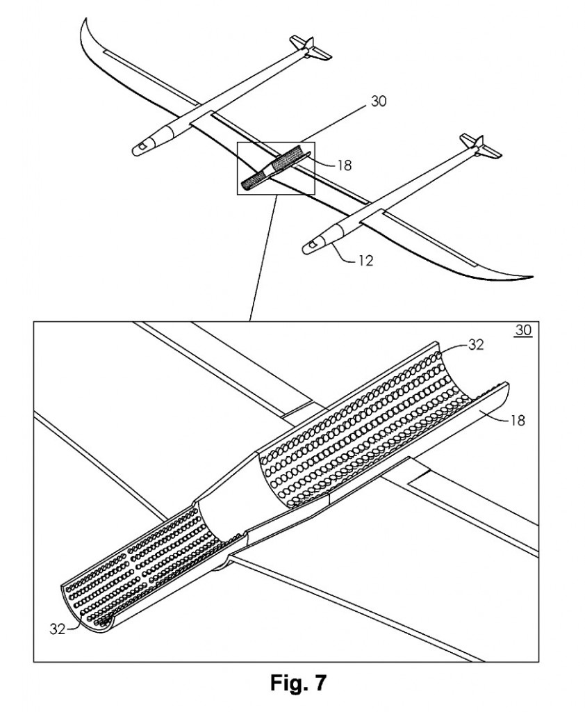
Where this gets interesting: the glider doesn’t drop the rocket, as you might expect. instead, the rocket is carried on the gliders “back.” At first blush this seems counter intuitive. The rocket has no wings, so if you simply cut it loose there’d be no reason for the rocket to lift upwards; at bet it’d slide aft in an unfortunate manner (as the CG of the assembly slide aft, all kinds of unfortunate responses can be expected). But an interesting trick would make this system work. When  the launch point is reached, the glider pitches upwards. This greatly increases the lift it generates while also greatly increasing both drag and the tension on the tow line. The glider would have a tendency to be “flung” upwards; the tow line is released. The glider has a serious excess in potential energy, which it expends by continuing to pitch upwards, eventually pointing roughly 50 degrees up. At the chosen point, straps holding the rocket in place are released. The rocket has rested in a form-fitting cradle; cushioning it were a multitude of “balloons.” These airbags formerly provided a wide-area shock absorber; now they serve to shove the rocket out of the cradle. Since the glider has pitched well upwards, positive separation should be relatively easy. Once separated, the glider pitches down again, leaving the rocket to boost to orbit.

And all the while the expensive stuff – the avionics, the jet engines, the crew – is relatively safe, far ahead in the towplane. If the rocket decides to turn itself into a fireball at any point, the towplane is well separated from it… 3500 feet of towline keeps a good clearance.

The dynamics of the system provides for some interesting effects. When the glider begins its pitch-up, it begins to describe a circular arc, rising above the tow plane. This necessarily means that it begins to accelerate both upwards and forwards relative to the two plane. Something like 25% of the kinetic energy of the tow plane is transferred to the glider and rocket payload, providing a velocity boost of 12% just when needed most.

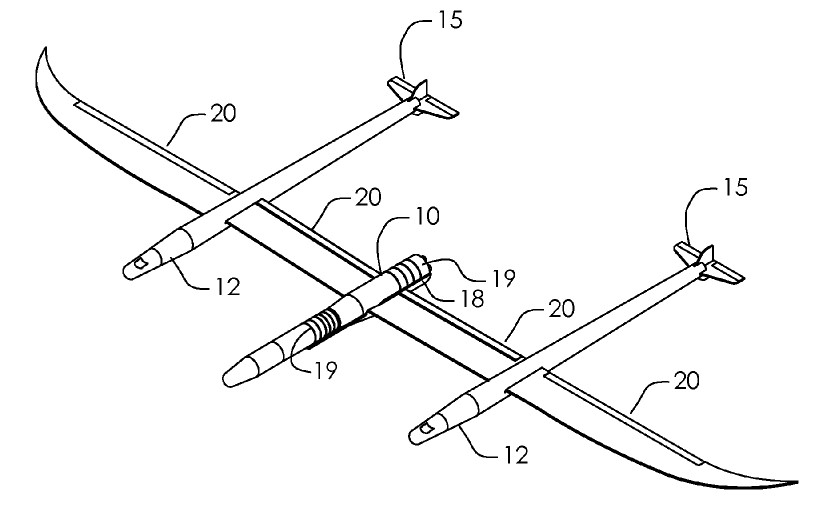
The glider is very clearly from the same design family as the White Knight One and Two carrier planes. It features twin fuselages  spread out on a long high aspect ratio wing with upward-curving, backward-bending wingtips. Dimensions and weights are not given, but scale can probably be determined by comparison with the DC-10 tow plane.

The basic aircraft configuration. Scale compared to the DC-10 is not necessarily accurate, but this is the best there is…

——————-

Isometric sketch of the glider. Family resemblance to *everything* Rutan is clear.

—————-

The balloon-lined launch cradle.

——————

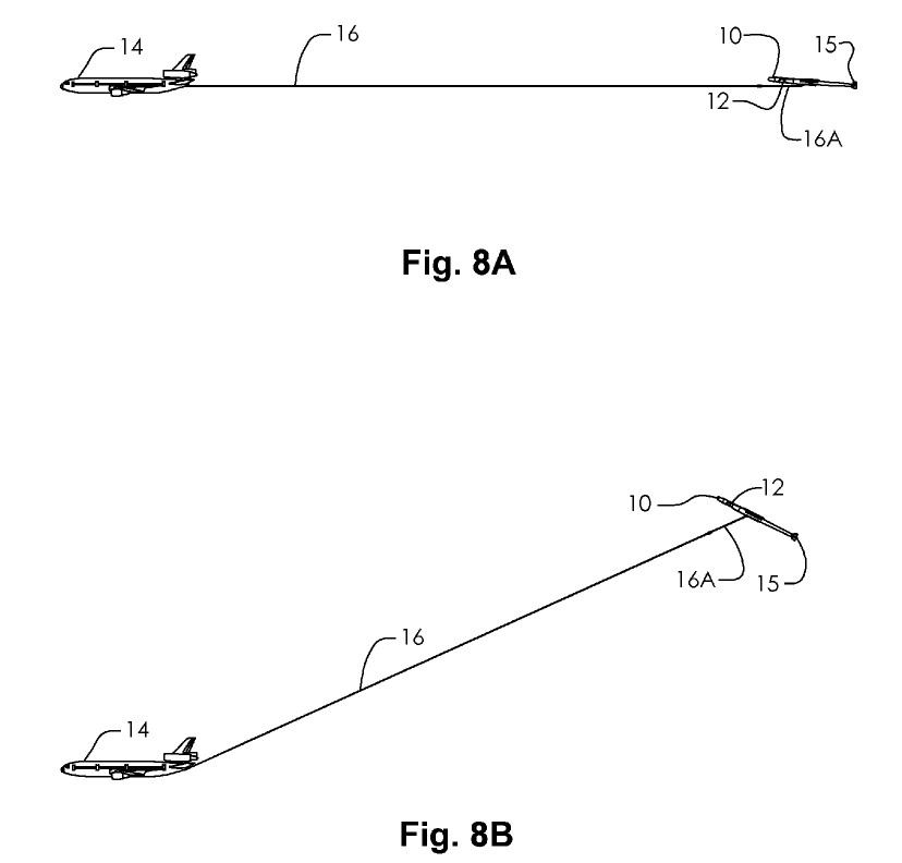
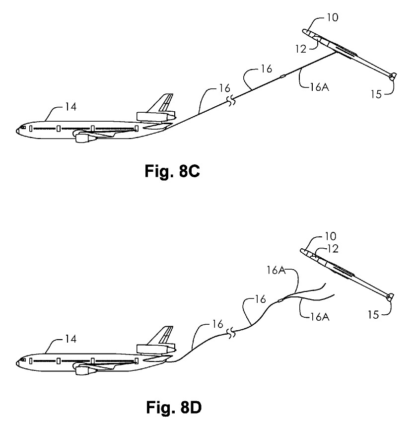
8A shows normal towing. 8B shows the configuration as the glider begins to climb, accelerating upwards while extracting kinetic energy from the tow plane.

———–

The moment when maximum flight path angle is reached and the tow line is cut loose.

———–

8F shows the holding straps being jettisoned, allowing the rocket to separate from the glider. 8G shows the glider pitching down as the rocket begins its boost to orbit.
————-
If you liked this review and/or found it useful, please consider helping out:
patreon

 Posted by at 5:57 pm
Jul 212014
 

For $10 patrons on my Patreon campaign, a new message should appear there asking you to vote on what I’ll release in August (two documents and one large format diagram). For those who are $10 patrons, here’s a partial list anyway… if you see something there and you really want to make sure it becomes available, well, the obvious thing to do is sign on and vote!

———————-

Drawing: fairly detailed 3-view of Lunar Roving Vehicle (as actually flown to the moon)

Drawing: “Plans for Scale Model Construction of the Honest John Surface-to-Surface Missile” by McDonnell-Douglas, 1971 (does anyone know of more of these???)

Document: “Douglas Aircraft Company: An Overview,” 60+ page brochure showing existing and proposed jetliners, by McDonnell-Douglas, ca. 1980

Art: a vintage lithograph of the Lockheed L-2000 SST in flight, w/3 view on the back.

Document: “CT-39 International Sabreliner,” a Rockwell International booklet/brochure describing the multipurpose utility jet

Document: “Air Force Expeditionary Catapult,” a truly massive billet of paper serving as a proposal from the All American Engineering Company for the System 300 Catapult, 1955. This was to be a turbojet-powered cable launching system for jet fighters which could be easily transported and set up in the field. (NOTE: this one counts as two reports, as it’s fairly gigantic)

Document: Aeroassisted Flight Experiment Nonadvocate Review, 1989, NASA

Document: Pocket Data for Rocket Engines, 1953, Bell

Document: SAM-D Air Defense Weapon System, 1973, US Army

Document: Pilots Handbook of Operation XLR11-RM-3 & XLR11-RM-5, liquid Rocket Engines, 1950, Reaction Motors

Art: X-15 lithograph (date unknown)

Document: The Centaur Program, 1961, Convair

Document: Orbiter Vehicle Structures, Rockwell

Document: An integrated Moonmobile-Spacesuit Concept, 1961, Aerojet

Document: The Intercontinental Stratoliner 707-320, 1955, Boeing

Document: Douglas DC-8 Design Study, 1953, Douglas

Document: Transport Weight Comparison Based on Lockheed 49-10, 1943, Lockheed

Document: ETR Launch Operations Plan for Cenaur on Shuttle, 1979, General Dynamics

Diagram: MD-11 wing diagram, six-feet long: McDonnel-Douglas, 1995

Document: A Lockheed presentation on the GL-224 Turbo-Jet VTOL Aircraft, 1958

Document: A Project RAND report on the GG-2 all-wing bomber, 1949

Document: A small Rockwell brochure on the “common core” concept for a fixed-wing subsonic B-1 variant, 1979 4) A presentation on the Douglas “Skybus,” 1944

Document: A NAA report on a turboprop-powered F-82E for ground attack, 1949

Document: A Curtis report on the twin engined F-87C, 1948

Document: A Vertol report on VTOL transport aircraft, showing several very different configurations, 1956

Document: A Lockheed presentation to the AIAA on the history of the Fleet Ballistic Missile, 1978

Document: A collection of Manned Spacecraft Center Space Shuttle orbiter concepts, 1972

Document: A Convair collection of design drawings of an Assault Seaplane, 1948 (NOTE: this one counts as two reports, as it’s fairly gigantic)

Document: A Vought report on the Regulus II missile with detailed diagrams, 1955
 Posted by at 3:41 pm
Jul 202014
 

I’m about $21 short of the next milestone, which will result in two “PDF reviews” per month of little-known online aerospace history resources. So if that idea appeals… consider signing up (and telling all your friends who have a few dimes to rub together).

Also: in August there will be three documents/large format diagrams released, along with three CAD diagrams. The documents/LFD’s are yet to be chosen (the $10 patron will get to vote on this in the next week or so), but the CAD diagrams are underway. One is already basically complete: the first accurate and clean, large 3-view diagram of the Northrop Tacit Blue demonstrator. The second will be of a proposed launch vehicle. The third is still up in the air.

 
patreon

 Posted by at 1:13 pm