May 242012
 

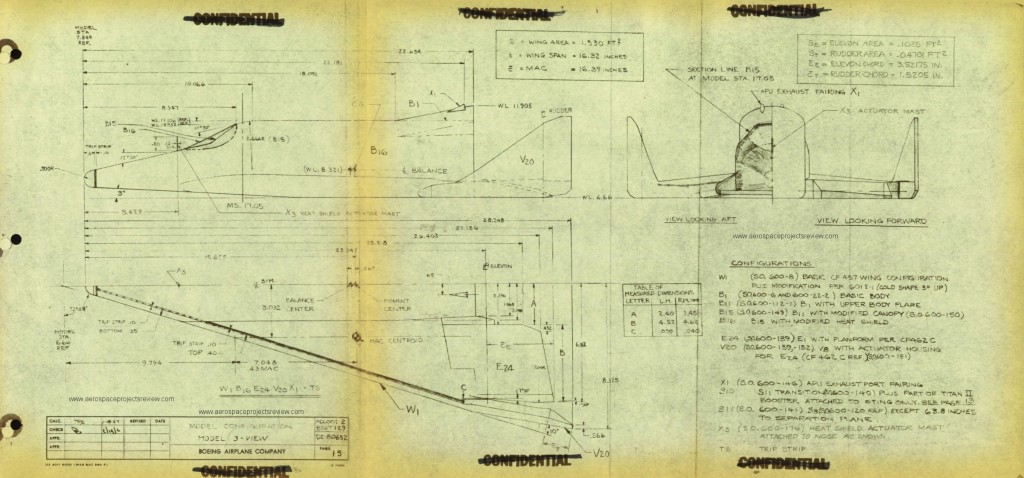
A 1962 Boeing diagram of the Model 844-2050 Dyna Soar configuration (almost the final configuration) as a 0.0666 scale wind tunnel model. Nothing too spectacular, but it does illustrate one detail rarely seen: the heat shield actuator mast.

The forward-facing windows were covered with an ejectable heat shield on the Dyna Soar until well after re-entry in order to protect them from excessive heating. The actuator mast would be a piston that would raise the front of the heat shield after the spaceplane had re-entered and slowed to subsonic; the “wind” would then get under the shield and lift it away from the spaceplane. I’ve seen very little on this mast… I don’t know if it would then retract, or if it would simply stay  in place through landing. None of the artwork I’ve seen has ever depicted it in any fashion… the heat shield is always there until it’s simply gone. Associated photos of the wind tunnel model do not show the mast.
 Posted by at 10:01 am
Apr 152012
 

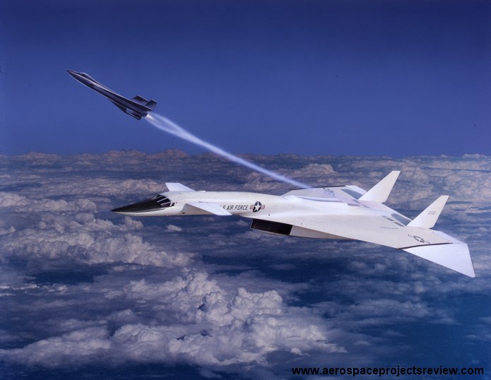
The proposed X-15A-3 was a stretched, delta-winged version intended for extended duration flight at Mach 6+. As with the X-15 and X-15A-2 versions, the plan was to launch the X-15A-3 from a B-52 underwing pylong. However, North American Aviation proposed launching it from atop a B-70 bomber. The theory was that the B-70 could get the X-15 up to around Mach 3 prior to separation, thus greatly improving the rocketplanes performance. However, launchign winged vehicles from the back of supersonic aircraft is non-trivially difficult… as the M-21/D-21 crash demonstrated.

The X-15A-3 shown here is an early design. The final version featured diamond-shaped wingtip fins.

You can download a 12 megabyte JPG file of the artwork; the link  is HERE. To access it, you will need to enter a username and password. The username: the first word in the body of the text on page 3 of APR issue V2N6. The password: the first word in the body of the text on page 4 of the same issue. Note that both are case sensitive.

 Posted by at 2:05 am
Apr 102012
 

This card shows an early (late 1980’s) McDonnell-Douglas design for NASP. A relatively fat lifting body design, this has many similarities to hypothetical “Aurora” hypersonic spyplane designs bandied about at the same time. This is not surprising… this NASP design is similar to any of a number of hypersonic configurations tested in NASA wind tunnels and shown publicly.

Note that the text on the back of the card describes a vehicle somewhat different than what NASP was supposed to be. The claim is made that the scramjets could power the vehicle Mach 25, orbital velocity… of they could allow the vehicle to cruise at Mach 6 for long range hypersonic transport. Early on in the program, the “Orient Express” was touted as a logical result of NASP work, but that quickly faded.

You can download 5.3 and 2.5 megabyte JPG files of the illustrations. The links to the JPG files are HERE and HERE. To access them, you will need to enter a username and password. The username: the first word in the body of the text on page 5 of APR issue V1N1. The password: the first word in the body of the text on page 11 of the same issue. Note that both are case sensitive.


 Posted by at 1:20 am
Apr 032012
 

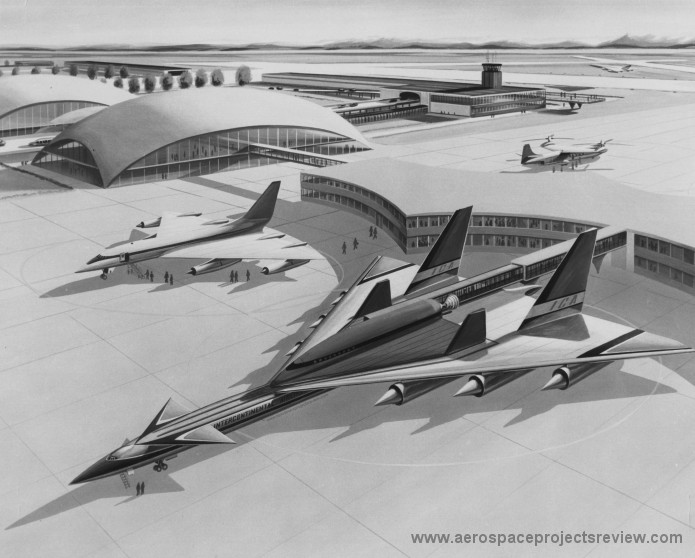
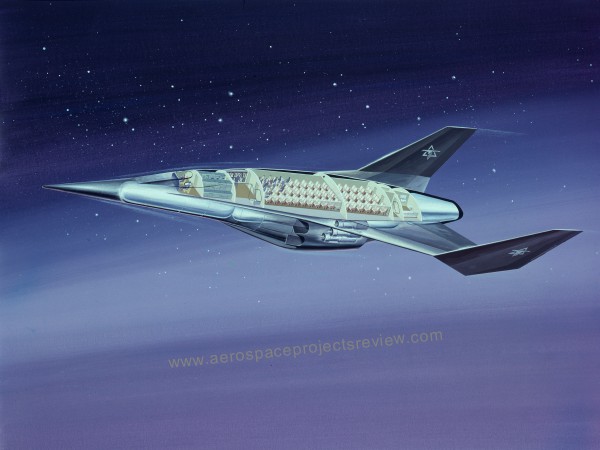
In 1960, Bell Aircraft released several paintings depicting a two-stage hypersonic passenger transport. The first stage was a multi-engined supersonic jet of fairly conventional configuration (though with very large 50,000 lb-thrust turboramjet engines), carrying on its back a rocket-powered second stage. The second stage was clearly influenced by Bell work on the Dyna Soar program.

The carrier would transport the second stage to an altitude of 20 miles and 5,300 mph. After release, the second stage would boost to 40 miles and speeds up to 15,000 miles per hour, permitting travel times from Los Angeles to Paris of one hour and four minutes for the thirty passengers on board. The vehicle was intended to enter service in the 1980-1990 timeframe.

Weight for the combined vehicle at takeoff would be 750,000 pounds. Span of the booster was 150 feet, length 200 feet. It’s unclear if this was a serious engineering design or purely speculative. Paintings and a display model show some notable differences.

You can download a 3 megabyte JPG file of the artwork; the link  is HERE. To access it, you will need to enter a username and password. The username: the first word in the body of the text on page 6 of APR issue V1N3. The password: the first word in the body of the text on page 23 of the same issue. Note that both are case sensitive.


 Posted by at 10:31 am
Mar 102012
 

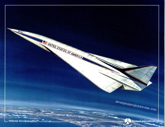
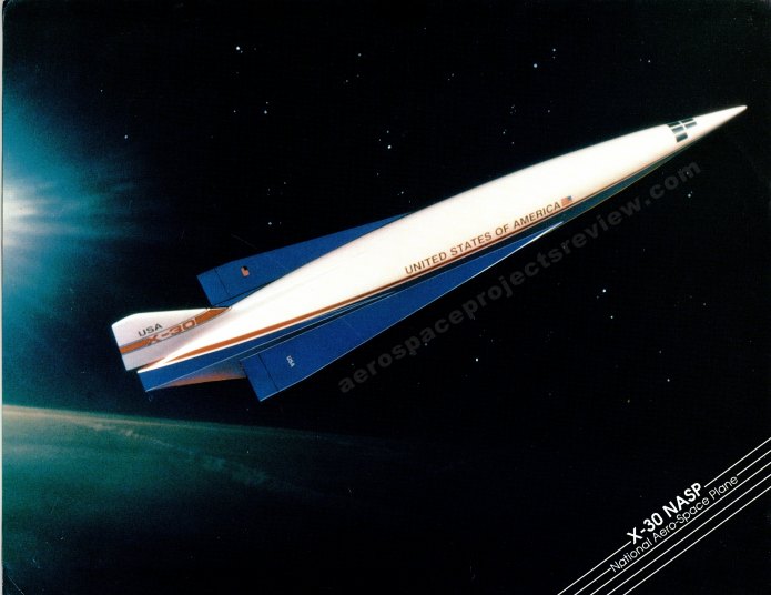
A Rockwell handout card (late 1980’s to 1990 or so) showing an artists impression of their early NASP configuration. This is the same design as shown HERE, but in painting rather than model form.

You can download 7.9 and 1.1 megabyte JPG files of the illustrations. The links to the JPG files are HERE and HERE. To access them, you will need to enter a username and password. The username: the first word in the body of the text on page 5 of APR issue V1N1. The password: the first word in the body of the text on page 11 of the same issue. Note that both are case sensitive.

 Posted by at 9:04 pm
Feb 282012
 

Another PR card showing an X-30 NASP configuration, this being a 1990 Rockwell configuration. It’s similar to but noticeably fatter than the earlier generic configuration (shown HERE).

You can download 6.7 and 2.2 megabyte JPG files of the illustrations. The links to the JPG files are HERE and HERE. To access them, you will need to enter a username and password. The username: the first word in the body of the text on page 5 of APR issue V1N1. The password: the first word in the body of the text on page 11 of the same issue. Note that both are case sensitive.

 Posted by at 12:31 pm
Feb 242012
 

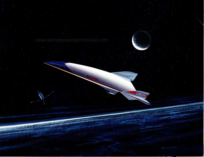
Another PR card showing an X-30 NASP configuration, this being an early design modeled off of the original du Pont configuration.

You can download 3.15 and 2.2 megabyte JPG files of the illustrations. The links to the JPG files are HERE and HERE. To access them, you will need to enter a username and password. The username: the first word in the body of the text on page 5 of APR issue V1N1. The password: the first word in the body of the text on page 11 of the same issue. Note that both are case sensitive.

 Posted by at 12:03 am
Feb 172012
 

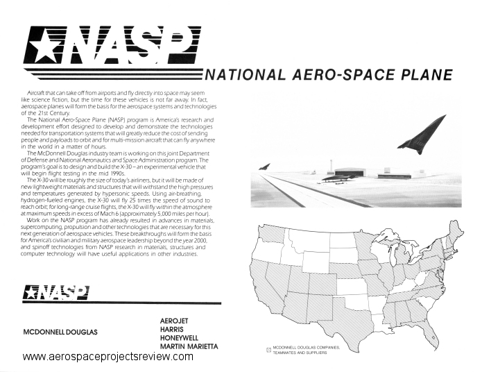
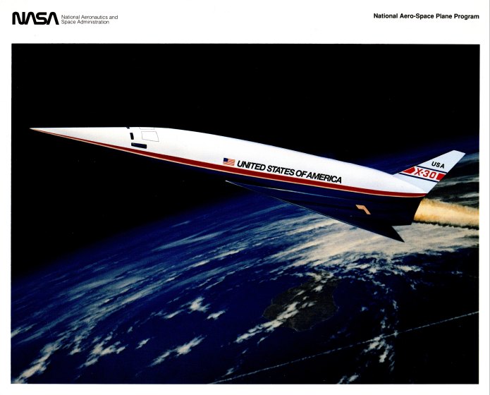
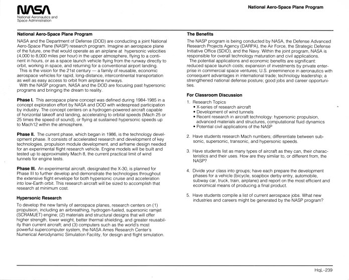
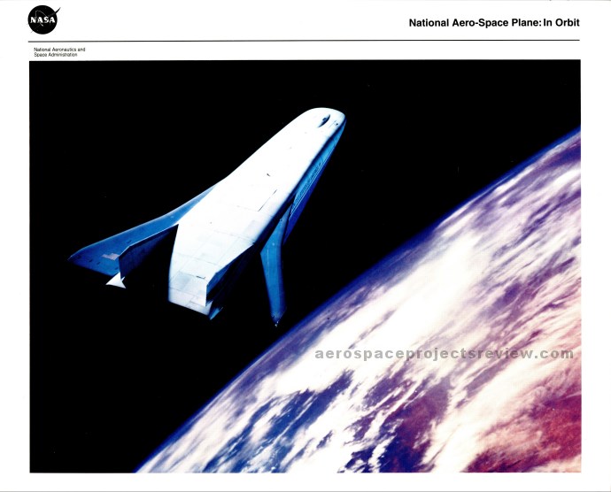
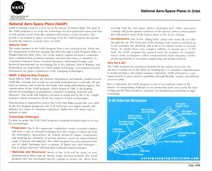
In the days before the web came to domination, aerospace companies and government organizations would stamp out glossy propaganda/PR informational cards by the truckload. The X-30 NASP (National Aero Space Plane) program was no different. Below is one such card released by NASA. Note that first flight was expected by 2000 or so… just slightly behind schedule at this point. The design shown here is the final publicly revealed configuration, with the wide flat “spatula” nose. Not shown in this – or pretty much any – illustration are the rocket engines needed to put the spaceplane into a circular orbit.

You can download 2.7 and 3.5 megabyte JPG files of the illustrations. The links to the JPG files are HERE and HERE. To access them, you will need to enter a username and password. The username: the first word in the body of the text on page 5 of APR issue V1N1. The password: the first word in the body of the text on page 11 of the same issue. Note that both are case sensitive.

 Posted by at 7:49 pm
Feb 142012
 

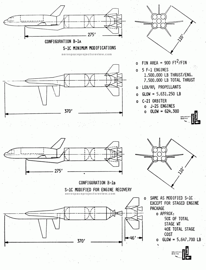
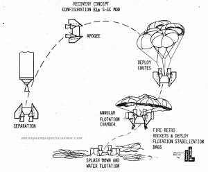
From 1970, a Grumman Alternate Space Shuttle design that utilizes the S-IC booster from the Saturn V. Quite a number of Space Shuttle concepts called for the S-IC to be used as a first stage booster, as an expendable stage, a partially reusable or fully reusable stage. Shown here, the basic S-IC would be expendable. However, a second option would be to use a modified S-IC where the outer four engines would drop off during ascent and would be recovered. This is the same concept that Boeing proposed for the S-ID stage (see the October 2008 issue of the AIAA-Houston “Horizons” newsletter for more on the S-ID).

The use of a S-IC – stock or modified for partial recovery – would have presented a number of advantages, not least being that the existing Saturn launch facilities could be used. The S-IC would have provided adequate launch performance; the use of recoverable engines would have lowered cost and increased performance. However, the S-IC production line had been shut down for some time, and restarting it would have proven not only politically dubious (restating the S-IC would have led to questions about restarting the rest of the Saturn/Apollo line), but also expensive.

 Posted by at 11:57 am
Feb 052012
 

Conceptual artwork from 1967 depicting a Mach 10 to Mach 14 hypersonic transport. Hydrogen burning scramjets would provide cruise propulsion at an altitude of 110,000 to 140,000 feet. No further data is available apart from what can be determined from the artwork. There are 136 seats, relatively few for an aircraft that is clearly quite large. The general configuration is similar to the hypersonic testbed previously posted HERE, especially the propulsion system & inlet arrangement.

You can download a 9.7 megabyte JPG file of the artwork; the link  is HERE. To access it, you will need to enter a username and password. The username and password are listed on page 2 of APR issue V0N0.  Note that both are case sensitive.

 Posted by at 7:38 pm