May 242012
 

A 1962 Boeing diagram of the Model 844-2050 Dyna Soar configuration (almost the final configuration) as a 0.0666 scale wind tunnel model. Nothing too spectacular, but it does illustrate one detail rarely seen: the heat shield actuator mast.

The forward-facing windows were covered with an ejectable heat shield on the Dyna Soar until well after re-entry in order to protect them from excessive heating. The actuator mast would be a piston that would raise the front of the heat shield after the spaceplane had re-entered and slowed to subsonic; the “wind” would then get under the shield and lift it away from the spaceplane. I’ve seen very little on this mast… I don’t know if it would then retract, or if it would simply stay  in place through landing. None of the artwork I’ve seen has ever depicted it in any fashion… the heat shield is always there until it’s simply gone. Associated photos of the wind tunnel model do not show the mast.

 Posted by at 10:01 am
May 132012
 

A cutaway diagram of a Boeing-Lockheed Space Shuttle concept derived from the Lockheed STAR Clipper design. This and other related concepts was covered in great detail in issue V3N2 of Aerospace Projects Review.

You can download a 1.5 megabyte version of this diagram; the link is HERE. To access it, you will need to enter a username and password. The username: the first word in the body of the text on page 8 of APR issue V3N2. The password: the first word in the body of the text on page 24 of the same issue. Note that both are case sensitive.

 Posted by at 1:35 pm
May 132012
 

In the late 1950’s, before NASA was created, the USAF, the US Army and even the US Navy each thought that they might lead the American manned space program. The Army produced studies for Project Horizon, a manned Lunar base for military purposes (not just research and exploration, but also offensive nuclear capability). Horizon would have used early versions of the Saturn I to send men and equipment into space. To land on the Moon, large landers such as the one shown below would have been used. This multi-stage monster would have had the Earth return capsule up top (the downward-pointing cone inside the nose), a feature carried forward on early NASA Apollo concepts until Lunar Orbit Rendezvous became the baseline.

 Posted by at 1:17 pm
May 032012
 

The Space Shuttle system was seemingly designed for modularity… the orbiter could be replaced, the boosters could be replaced. Payload shrouds could be placed alongside the tank in place of the orbiter, or on the nose of the external tank either replacing the orbiter or supplementing it.

Martin calculated that the payload for the standard Shuttle using lightweight fiber wound solid rocket boosters and a lightweight ET going to a 215 nautical mile orbit would be 60,800 pounds. Payload to the same orbit would increase to 69,700 pounds if the ET was taken all the way to orbit (the more efficient SSMEs would be used all the way to orbit rather than relying on the OMS engines). By using the ACC and dragging the ET and ACC all the way to orbit, total payload would be 60,100 pounds.

A brochure from Martin Marietta describing the ACC is available HERE.

 Posted by at 6:33 pm
Apr 292012
 

A 1962 study by North American Aviation produced designs for the Apollo Service Module designed to mate directly to the 260-inch-diameter Saturn S-IVb and other stages. At the request of the NASA Manned Spacecraft Center (later known as the Johnson Space Center), NAA studied whether it would be advantageous to increase the 154-inch base diameter of the Service Module.

In short, the wider vehicle was found to be aerodynamically superior than the baseline configuration when used on the Saturn C-5 (later known as the Saturn V), but aerodynamically inferior when used on the Little Joe II test vehicle and the early Saturn C-1. Additionally, the engine would be easier to install, inspect and maintain; the conical surface was better for the radiators, and the larger moment arm improved performance of the reaction control system. Unfortunately, the wider service module would be about 1000 pounds heavier at burnout than the 154-inch baseline, and the lunar module adapter would have to be notably heavier as well. Given the primary importance of mass in the Apollo program, this result was probably the most important.

Two 260-inch diameter configurations.


 Posted by at 10:18 pm
Apr 212012
 

This design was featured in the F-23 derivatives article in the recent V3N2 issue of Aerospace Projects Review. This was Northrops plan for an operational follow-on to the YF-23, with some notable geometry changes.

You can download a 2.5 megabyte GIF file of the diagram. The link to the JPG file is HERE. To access it, you will need to enter a username and password. These are available on the first page of the Aerospace Projects Review V3N2 Addendum (available HERE) Note that both are case sensitive.

 Posted by at 10:12 pm
Apr 152012
 

The proposed X-15A-3 was a stretched, delta-winged version intended for extended duration flight at Mach 6+. As with the X-15 and X-15A-2 versions, the plan was to launch the X-15A-3 from a B-52 underwing pylong. However, North American Aviation proposed launching it from atop a B-70 bomber. The theory was that the B-70 could get the X-15 up to around Mach 3 prior to separation, thus greatly improving the rocketplanes performance. However, launchign winged vehicles from the back of supersonic aircraft is non-trivially difficult… as the M-21/D-21 crash demonstrated.

The X-15A-3 shown here is an early design. The final version featured diamond-shaped wingtip fins.

You can download a 12 megabyte JPG file of the artwork; the link  is HERE. To access it, you will need to enter a username and password. The username: the first word in the body of the text on page 3 of APR issue V2N6. The password: the first word in the body of the text on page 4 of the same issue. Note that both are case sensitive.

 Posted by at 2:05 am
Apr 132012
 

Dates from the late 80’s or early 90’s.

You can download a 3 megabyte JPG file. The link to the JPG file is HERE. To access it, you will need to enter a username and password. The username: the first word in the body of the text on page 13 of APR issue V3N1. The password: the first word in the body of the text on page 21 of the same issue. Note that both are case sensitive.

 Posted by at 12:14 am
Apr 102012
 

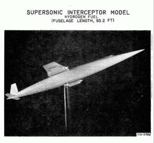
From the Fifth Semiannual Report to Congress (NASA, 1961) comes a photo of a supersonic transport wind tunnel model. This configuration would have been quite difficult to translate into a practical airliner design; while the dedication to area ruling would have made it quite low drag at supersonic, it would have made manufacturing a nightmare. Additionally, the severe wasp-waisting of the fuselage would have made not only the structural design of the pressure vessel a challenge, it would have made the passenger seating layout quite a mess.

 Posted by at 11:56 pm