This subject has been mentioned on this blog before (way back in 2008, 2012, and 2013), but here’s a brand-new video covering the subject of the inconel foil insulation that protected the F-1 engines on the Saturn V when they flew. This insulation was rarely seen by the public and made the engines look entirely different from what people were used to, because the insulation was something of a last-minute addition to help counter some severe heating cause by exhaust gas recirculation as well as direct thermal radiation roasting of the central engine.
A video where some guys get into the archives of the US Space & Rocket Center in Huntsville, Alabama. On display is a sizable (looks like about 1/50 scale) Space Shuttle, ET and Boosters made from plexiglas. It is a thing of beauty, surely a chore and a half for the model shop back in the day. This is *not* the final Shuttle design; some differences are obvious such as the split cargo bay doors and, while unmentioned in the video, the existence of extended OMS pod fairings, reaching out onto the aft of the cargo bay doors.
Last time I visited the USS&RC in something like 2005 they had a much bigger plexiglas STS model on public display, something like 1/10 scale, along with a gigantic plexiglas Saturn V. Such things are fantastic artifacts, and if you are working on a complex engineering project like this a see-through plexiglass large scale model is terribly helpful. I suspect that such things are only rarely made these days, as computer graphics are a lot easier, cheaper and more readily updatable. But nothing beats a Real Thing. And at least so far, 3D printing is not up to the job of stamping out large-scale transparent models like this. But someday…
The Air Force Research Lab has released a half-heartedly CGI animated video showing the X-60A hypersonic research vehicle designed by Generation Orbit. This is a small unmanned missile to be carried to release altitude underneath a modified Gulfstream III corporate jet, where it would fire its own throttleable liquid rocket engine and climb to cruise altitude (~130,000 ft). The vehicle is fitted with an unconventional set of wings and control surfaces; it’s not immediately clear just what it’s supposed to do other than go fast. One would imagine that high-Mach airbreathing propulsion systems would be of interest to the USAF these days, and scramjet technology is mentioned as part of the proposed payload, but how such equipment would be integrated into the vehicle is unclear.
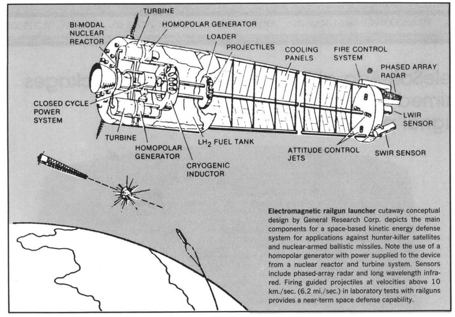
An illustration from 1984 showing the main features of an orbital railgun for the Strategic Defense Initiative program. While the design looks reasonable enough, almost certainly this is either missing a whole lot of important details or has changed them into unrecognizability. Scale is impossible to determine, but a practical space-based railgun capable of generating the projectile velocities needed (typically 10 km/sec) would have been an impressive structure indeed.
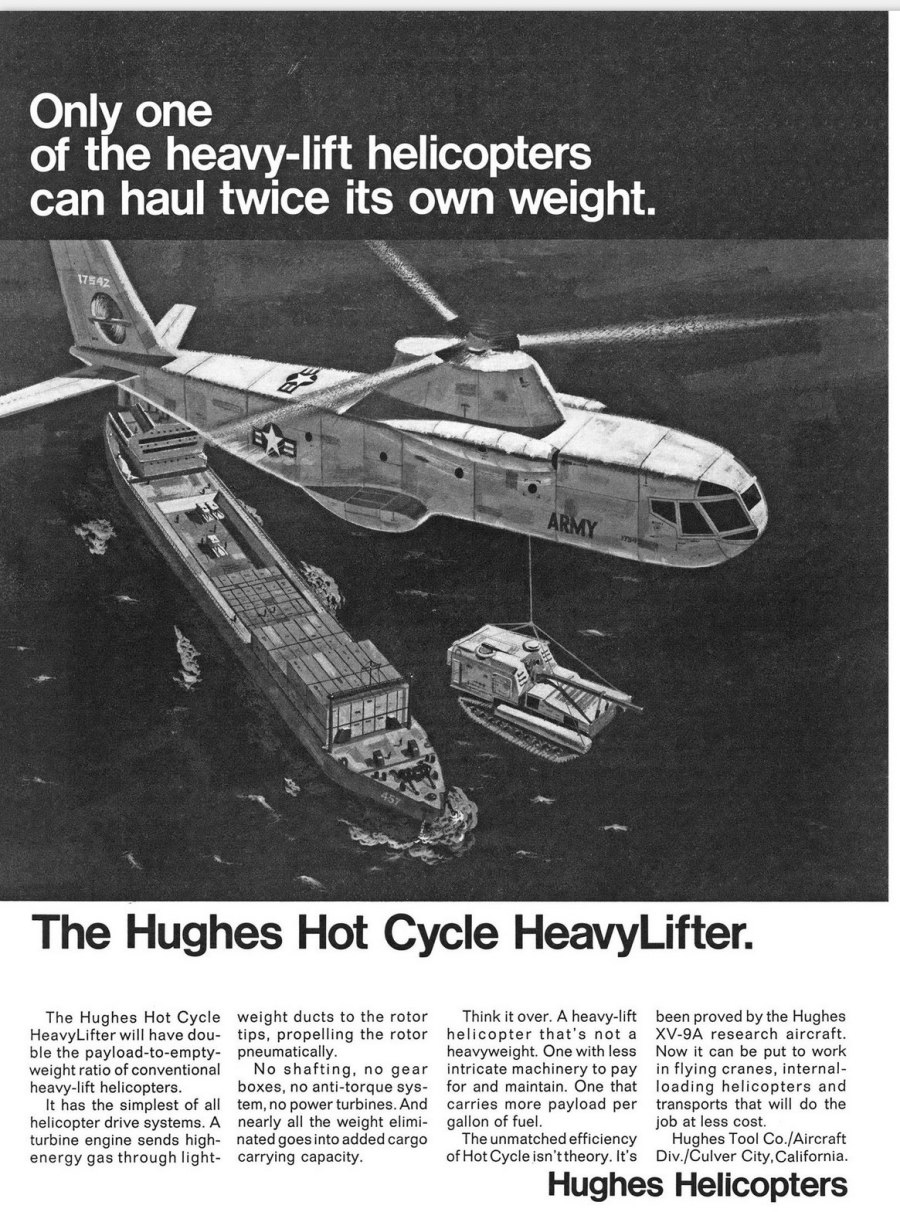
A magazine ad from 1967 showing a concept for a “Hot Cycle” helicopter. The “hot cycle” was a way to spin the rotors without imparting a massive torque to the fuselage as usually happens with helicopters, requiring a tail rotor to counter. here, instead of mechanically linking the engine to the rotor via drive shafts and gears, the engine exhaust was ducted up through the central rotor shaft, then out to the tips of the rotors, and then ejected through thrust-generating nozzles. This would impart only a trivial amount of torque to the fuselage, largely from friction with the shaft bearings. it was a great idea, but there were some issues with leakage around the bearings as well as being impressively loud and fuel-hungry.
Note that while the “hot cycle” eliminated the great majority of the need for an anti-torque tail rotor, this and similar designs still had one. This tail rotor would be used to swing the tail back and forth, yawing the aircraft at low speed.. This woudl require that the rotor be able to provide thrust in either direction on demand.
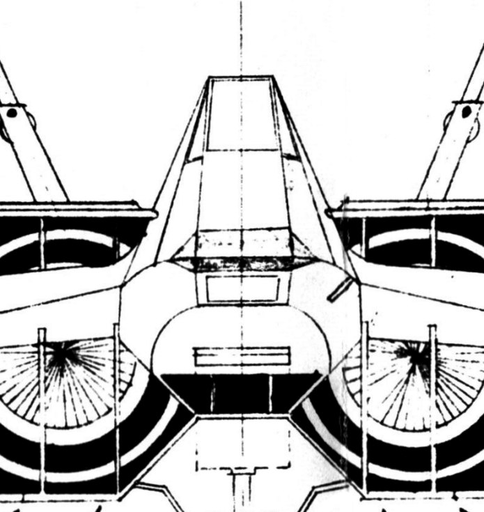
As a bonus for those who subscribe to the APR Patreon or the APR Monthly Historical Documents Program at above the $10 level, I have made available a diagram I photocopied several decades ago at the US Air Force Museum archive: a detailed and seemingly accurate three-view of the MiG-31 “Firefox” from the movie of the same name. I *think* it’s “fan art,” but am not sure… but the USAF thought that it was worth archiving. If this is of interest, consider subscribing at the $11 level of higher.
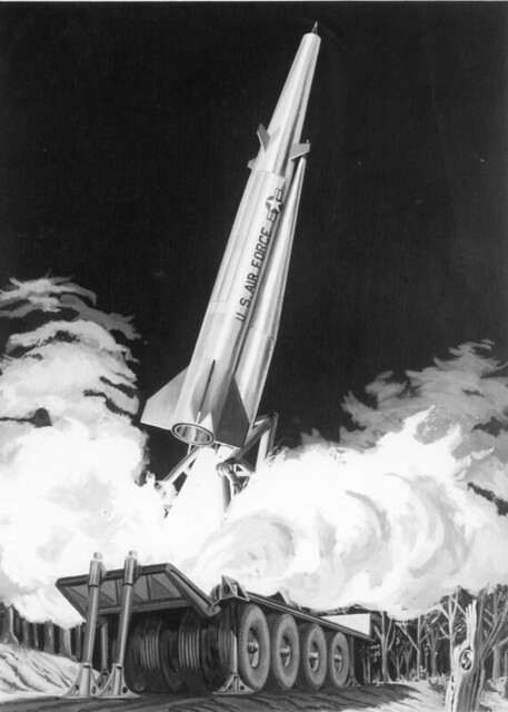
The San Diego Air and Space Museums Flickr account recently added this illustration, showing a Convair “Big Stick” being launched off the back of mobile transporter. “Big Stick” was a Convair concept for a nuclear ramjet powered cruise missile of nearly unlimited range, a less-known competing design against Voughts Pluto vehicle.
A higher rez (though, sadly, not a whole lot higher) version is available HERE.
If you are interested in Big Stick and Project Pluto, I recommend Aerospace Projects Review issue V2N1, which covers both in detail.
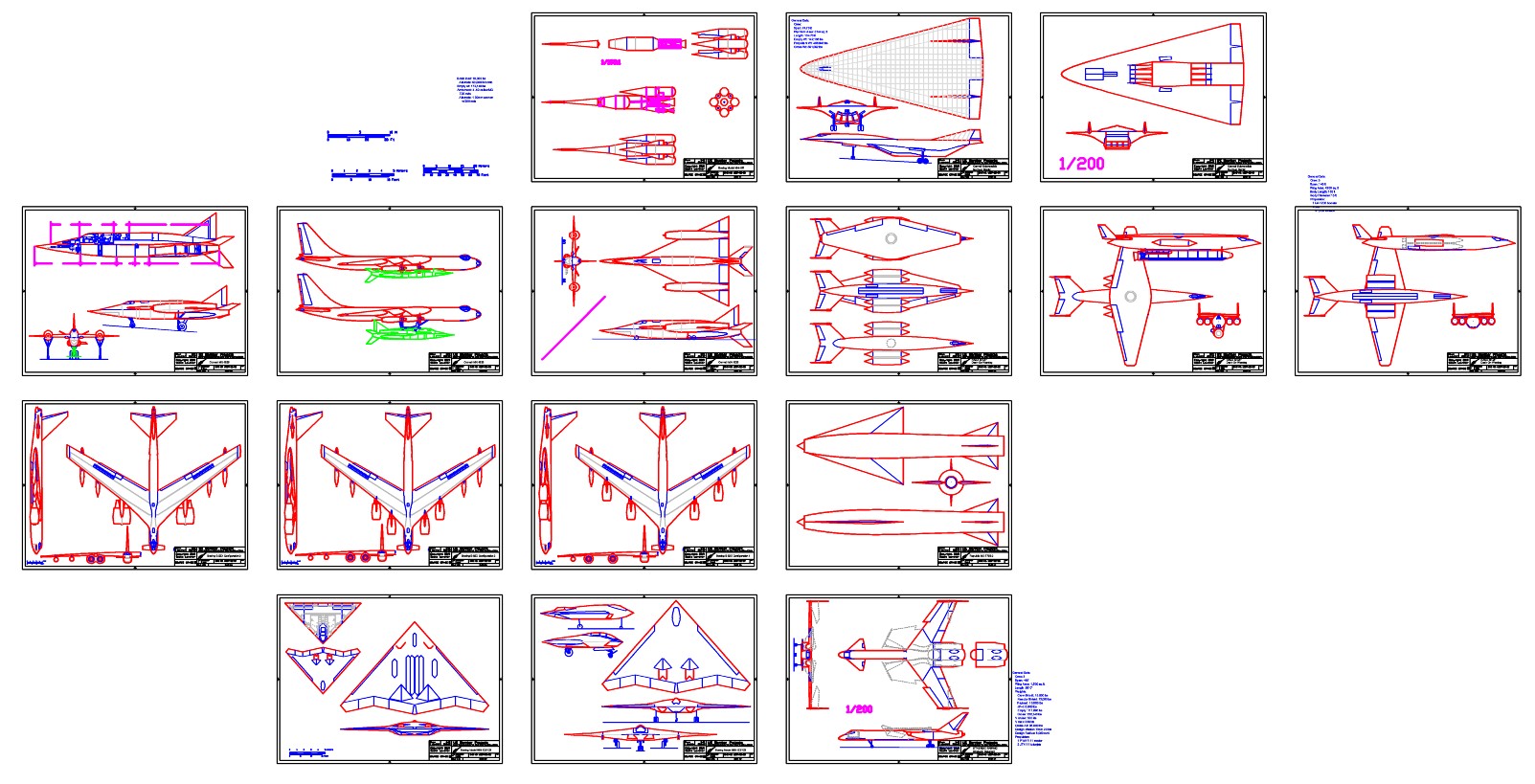
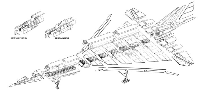
Lockheed’s entry into the FAA’s 1960’s Supersonic Transport contest was the L-2000. It was an appealing design, sort of a super-sized and angular Concorde. it lost to the Boeing 2707 due in no small part to the 2707’s swing wings… wings which wound up being fixed, like those of the L-2000.
In 1965 Lockheed released an exploded view of the L-2000’s structure, reproduced in Aviation Week, split across two pages. I took the images and fixed them; the full-size end result is pretty spiffy. I have uploaded the illustration, and two additional L-2000 images to the 2019-02 APR Extras Dropbox folder, available to $4 and up subscribers to the APR Monthly Historical Documents Program.