I’ve recently figured out how to get reliably good-quality vector graphic PDF files from my AutoCAD diagrams.These differ from standard “raster” graphics like GIFs and JPGs in that they are composed of scalable lines rather than pixels; this means that they can be printed off at many scales and they’ll retain clarity.
I think a lot of the diagrams would look quite good printed in large format; I’ve previously mentioned that I’m working on a few diagrams specifically for printing off on large format (24X36) mylar, but I’ve others that I think would also look good scaled for 18X24. I’m making these first seven diagrams available, formatted and scaled for 18X24. They can be viewed on screen, printed on a standard printer or printed by a large format printer all with equal clarity.
If this idea appeals, be sure to tell your friends, family, foes, anyone you think might be interested. Also be sure to comment if there are any diagrams I’ve previously created for APR, USXP or elsewhere that you’d like to see in this format. Some of them would be best as multi-sheet diagrams. Suggestions on how to improve also appreciated.
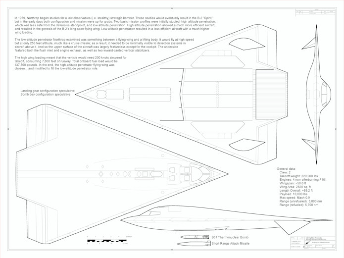
CAD 007: Northrop Low Altitude Penetrator
A 1/72 diagram of a 1979 design for a B-2 alternate configuration
Download for $3
———————————
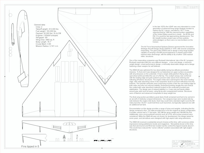
CAD 006
A 1/96 scale diagram of the 1979 Rockwell D645-4a spanloader bomber.
Download for $3
CAD 005
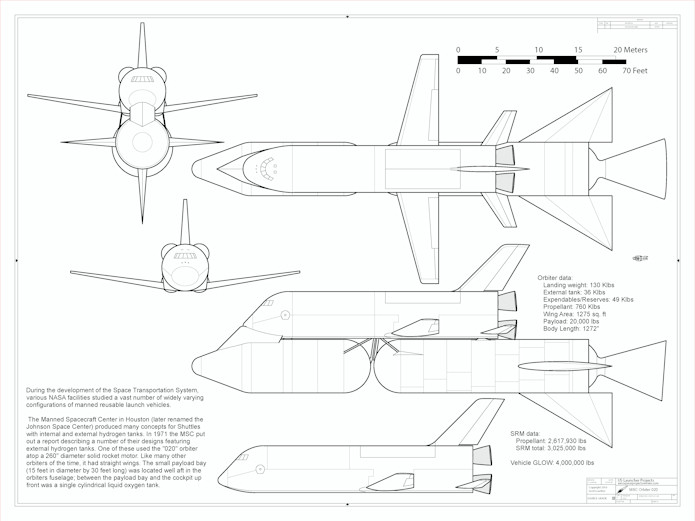
A 1/144 scale diagram of the Manned Spacecraft Center MSC Orbiter 020, a 1972 Space Shuttle concept with a single 260″ solid rocket booster.
Download for $3
CAD 004
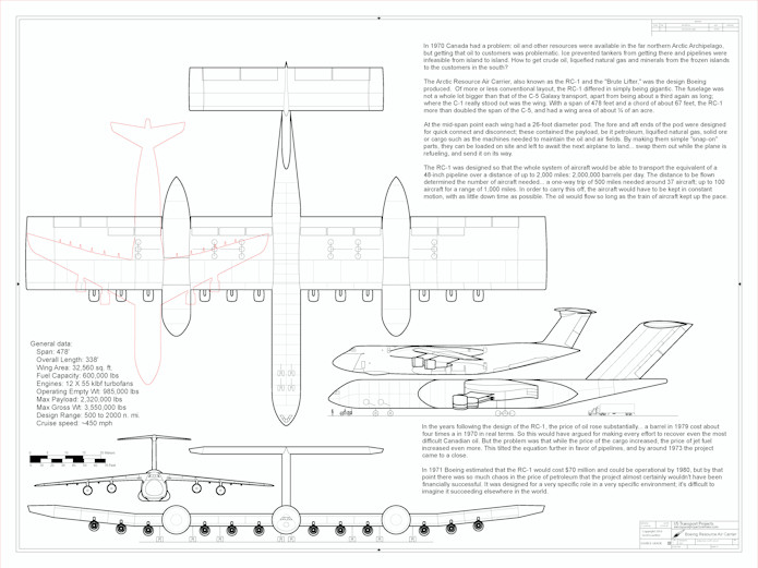
A 1/350 scale diagram of the 1971 Boeing Resource Air Carrier (AKA RC-1, AKA “Brute Lifter”) designed as a flying oil tanker for the arctic.
Download for $3
CAD 003
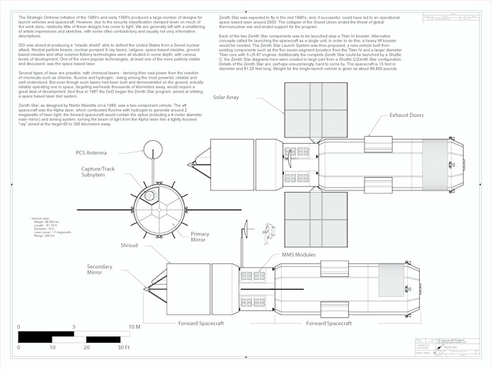
A 1/72 scale diagram of the Martin-Marietta “Zenith Star” experimental space-based laser for the Strategic Defense Initiative.
Download for $3
CAD 002
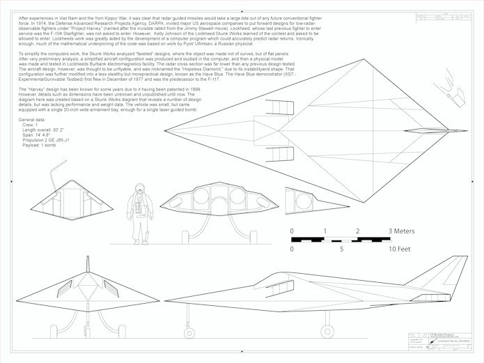
A 1/24 diagram of the Lockheed “Harvey,” the initial concept for a low radar cross section strike platform that eventually became the F-117.
Download for $3
———————————
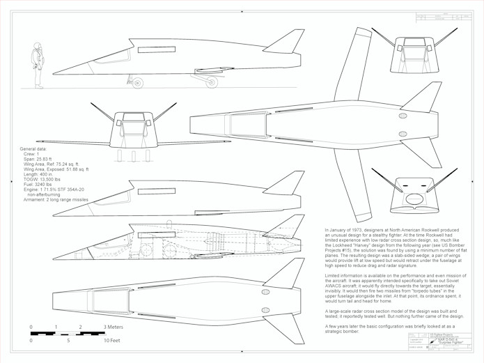
CAD 001
A 1/32 diagram of the North American Rockwell D-541-4 “Surprise Fighter” from 1973, an early stealth concept designed to sneak up on Soviet AWACS planes.
Download for $3
Download all seven for $18.90 (10% off)